Automatic production all-in-one machine for penetrating pulling head into zipper

A technology of wearing and pulling a head and an integrated machine, which is applied in the directions of sliding fastener components, applications, fasteners, etc., can solve the problems of low assembly efficiency, high rejection rate, error-prone, etc., and achieve the effect of high operation efficiency and simple structure.

Active Publication Date: 2019-05-10
池州美利达智能装备科技有限公司
View PDF12 Cites 3 Cited by
  • Summary
  • Abstract
  • Description
  • Claims
  • Application Information

AI Technical Summary

Problems solved by technology

However, the assembly of the zipper puller and the zipper cloth of this type of zipper is still carried out manually. The specific operation: the worker punches a gap on the zipper cloth with a punch, then penetrates the zipper head from the gap, and then cuts the zipper cloth according to needs. The length is cut to a specified length, and it is easy to make mistakes in the manual assembly process. If the zipper puller and the zipper fabric are dislocated, it is difficult to separate the zipper puller from the zipper fabric. Therefore, manual assembly is not only low in assembly efficiency, but also has a high scrap rate, which increases production. cost

Method used


Image

  • Automatic production all-in-one machine for penetrating pulling head into zipper
  • Automatic production all-in-one machine for penetrating pulling head into zipper
  • Automatic production all-in-one machine for penetrating pulling head into zipper

Examples


Embodiment 1

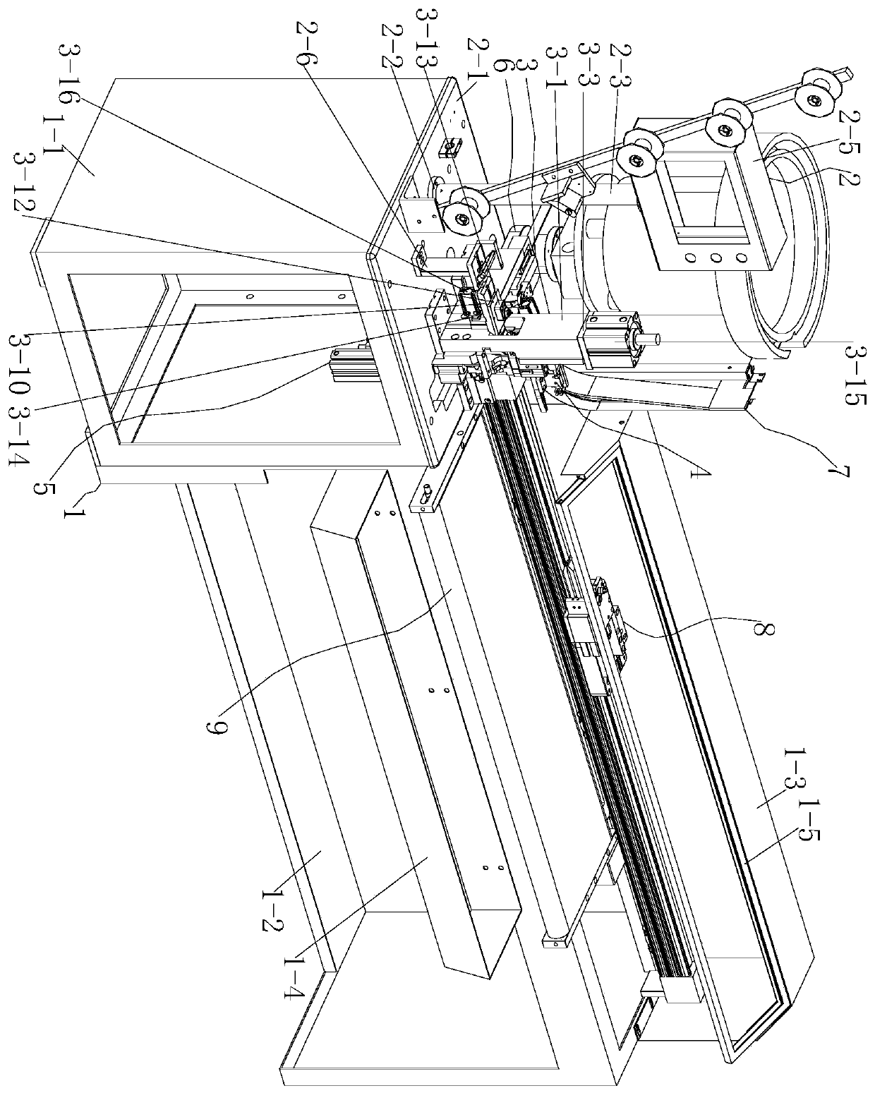
[0055] Start the cut-off function first, and cut off the piston rod of the cylinder 3-15 to move downwards, because the cut-off cylinder connection block 3-4 is connected with the piston rod end of the cut-off cylinder 3-15, and the cut-off cylinder connection block 3-4 is connected with the piston rod end of the cut-off cylinder 3-15. The upper end of the cutting slider 3-5 is clamped, the upper cutting knife 3-6 is tightly connected to the lower end of the cutting slider 3-5, and the lower cutting knife 3-7 is tightly connected to the lower end of the large sliding box 3-1, Therefore, the piston rod of the cut-off cylinder 3-15 moves down together with the cut-off cylinder connection block 3-4, the cut-off slider 3-5 and the cut-off upper knife 3-6, and then the zipper cloth is cut off by the upper knife 3-6, and then Cut off the piston rod of the cylinder 3-15 and move upwards to reset, this step operation has guaranteed the flatness of the cut surface of the zipper cloth. ...

Embodiment 2

[0058] The induction seat 4-5 is provided with a contact sensor, and the piston rod of the large cylinder 5-11-1 is pushed up, because the main seat 5-1 of the lower mold is provided with a guide rail 5-1-1, The guide rail one 5-1-1 slides and is provided with a slider one 5-1-2, and the movable block 5-2 of the lower mold is tightly connected with the slider one 5-1-2, and the slider mold A5 -3 is tightly connected to the middle of the side of the lower mold movable block 5-2, the slider mold B5-4 is tightly connected to the middle of the upper end of the lower mold movable block 5-2, and the connecting block 5-5 is fastened to the Between the slider mold A5-3 and the slider mold B5-4, the link plate 5-6 is tightly connected to the upper end of the side of the slider mold A5-3, and the slider baffle plate 5-7 is connected to the slider mold The center of the upper end of A5-3 is tightly connected, so the movable block 5-2 of the lower die moves upward along the guide rail 1 5...

Embodiment 3

[0063] The piston rod of the large cylinder 5-11-1 is pushed up, and the lower mold movable block 5-2 moves upward along the guide rail 1 5-1-1 with the parts connected with the lower mold movable block 5-2. When the corresponding contact sensor on the induction pin 4-9 turns off the light, it proves that there is no slider on the lower membrane assembly 5, and then the piston rod of the large cylinder 5-11-1 shrinks and resets, and at the same time pushes the cylinder 7-14-1 The piston rod shrinks, because the push rod 7-9 is slidingly connected with the push rod slide box 7-10, and the slider limit block 7-14 and the connecting block 7-13 are tightened on the push rod 7-9 At the end, the "I" buckle 7-15 is clamped with the slider limit block 7-14, and the upper end of the push rod sliding box 7-10 is fastened with a push cylinder 7-14-1. The pushing card 7-11 is tightly connected with the end of the pushing rod 7-9, and the pushing plate baffle 7-12 is tightly connected with...


PUM


Abstract

The invention discloses an automatic production all-in-one machine for penetrating a pulling head into a zipper. The all-in-one machine comprises a machine case assembly, a panel assembly, a cut-off assembly, an upper mold assembly, a lower mold assembly, a feeding assembly, a pull head track assembly, a clamp assembly, a conveying belt assembly, a vibration disc assembly, a chain guiding frame assembly and an outer rail assembly, wherein the cut-off assembly is in tight connection with the panel assembly, the upper mold assembly is in tight connection with the cut-off assembly, the lower moldassembly is in tight connection with the cut-off assembly, the feeding assembly is in tight connection with the panel assembly, the pull head track assembly is in tight connection with the panel assembly and is connected with the vibration disc assembly, the clamp assembly is in sliding connection with the outer rail assembly, the conveying belt assembly is in tight connection with the machine case assembly, the vibration disc is in tight connection with the panel assembly, and the chain guiding frame assembly is in tight connection with the upper end of the panel assembly. According to the automatic production all-in-one machine, the automatic penetrating operation of the zipper head is realized and is convenient, the efficiency is high, the manual operation is not required, a waste product is not produced in the assembling process of zipper cloth and the zipper head, and the rejection rate is decreased.

Description

technical field [0001] The invention belongs to the technical field of automation equipment, in particular, the invention relates to an automatic zipper threading slider production integrated machine. Background technique [0002] Zippers are all provided on existing clothing and bags, so they are widely used. However, the assembly of the zipper puller and the zipper cloth of this type of zipper is still carried out manually. The specific operation: the worker punches a gap on the zipper cloth with a punch, then penetrates the zipper head from the gap, and then cuts the zipper cloth according to needs. The length is cut to a specified length, and it is easy to make mistakes in the manual assembly process. If the zipper puller and the zipper fabric are dislocated, it is difficult to separate the zipper puller from the zipper fabric. Therefore, manual assembly is not only low in assembly efficiency, but also has a high scrap rate, which increases production. cost. [0003] T...

Claims


Application Information

Patent Timeline
Patent Type & Authority Applications(China)
IPC IPC(8): A44B19/62
CPCY02P70/10
Inventor 魏礼风季顺庆
Owner 池州美利达智能装备科技有限公司
Why Eureka
Try Eureka