
A clinical limb rehabilitation device

A rehabilitation device and limb technology, applied in passive exercise equipment, physical therapy, etc., can solve the problems of increased workload, muscle atrophy, unfavorable recovery, etc., and achieve the effect of reducing work intensity, good comprehensiveness, and strong practicability

Active Publication Date: 2021-05-07
王尚超
View PDF24 Cites 3 Cited by
  • Summary
  • Abstract
  • Description
  • Claims
  • Application Information

AI Technical Summary

Problems solved by technology

[0002] After treatment, patients generally have limb dysfunction and need to rest in bed, but long-term rest will also bring certain adverse reactions to the body, resulting in weakness, which is not conducive to future recovery, and there is a certain sub-health state. For patients who are relatively light or have recovered to a certain extent and do not need to rest, a certain intensity of strength training is necessary, otherwise long-term bed rest will cause muscle atrophy, joint stiffness, and even cause disuse paralysis of the patient's limbs, which will affect the patient's health and is not conducive to The recovery of patients in the later stage, so it is very important for the rehabilitation treatment of surgical patients such as limb dysfunction, and it is necessary to provide targeted and convenient recovery devices
[0003] Existing patients are generally unable to move after treatment, and can only lie still, relying on the help of surgical medical staff to move their limbs, which not only brings great inconvenience to the medical staff, but also increases the workload. The general structure of the device is relatively simple, it is not easy to adjust, and it cannot be well matched to patients of different heights, and generally only has the function of upper limb or lower limb rehabilitation training. For this reason, we propose a clinical limb rehabilitation device

Method used


Image

  • A clinical limb rehabilitation device
  • A clinical limb rehabilitation device
  • A clinical limb rehabilitation device

Examples


Embodiment Construction

[0015] The following will clearly and completely describe the technical solutions in the embodiments of the present invention with reference to the accompanying drawings in the embodiments of the present invention. Obviously, the described embodiments are only some, not all, embodiments of the present invention.

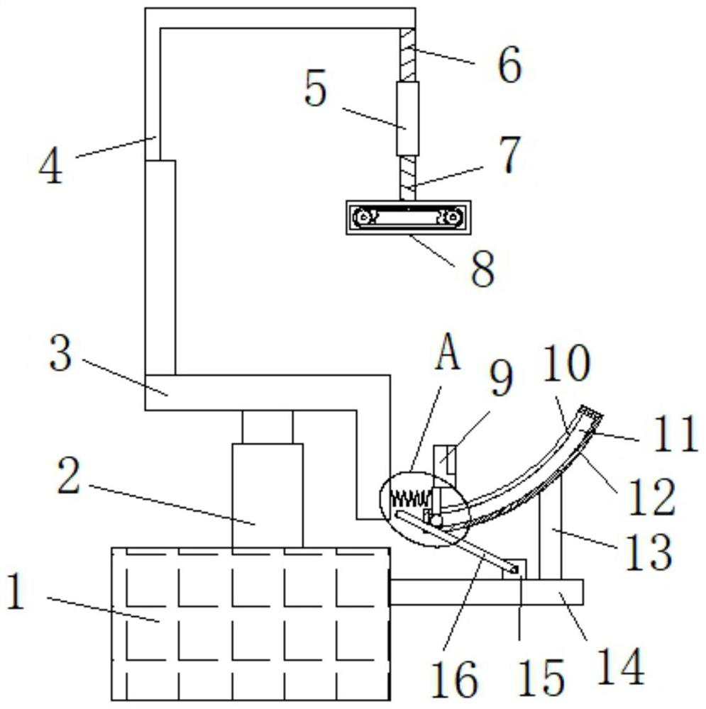
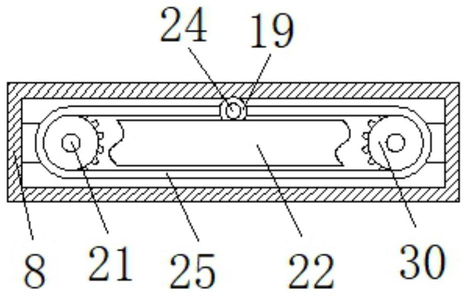
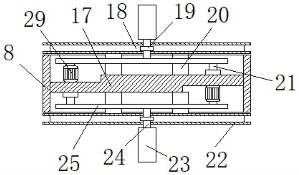
[0016] refer to Figure 1-4 , a clinical limb rehabilitation device, comprising a base 1, the upper end of the base 1 is provided with a seat 3, the upper end of the base 1 is provided with a hydraulic rod 2, the upper end of the hydraulic rod 2 is fixedly connected with the seat 3, and can The height is adjusted to meet different use requirements. The upper end of the seat 3 is provided with an L-shaped rod 4, the lower end of the L-shaped rod 4 is connected with an exercise device, the lower end of the L-shaped rod 4 is provided with an upper screw 6, and the lower end of the upper screw 6 The threaded pipe 5 is connected in rotation, and the lower end of the threa...


PUM


Abstract

The invention relates to the technical field of medical devices, in particular to a clinical limb rehabilitation device, which includes a base, a seat is arranged on the upper end of the base, an L-shaped bar is arranged on the upper end of the seat, and the lower end of the L-shaped bar is connected to There is an exercise device, the output shaft of the first motor is connected with a long rod, the upper end of the support rod is provided with an arc block, the upper end of the arc block is provided with a groove, and the side wall of the arc block There is an arc-shaped groove connected to the groove, the upper end of the groove is inserted with a fixed plate, the lower end of the fixed plate is provided with a support shaft matching the arc-shaped groove, and the support shaft matches the long rod, The upper end of the fixed plate is provided with Velcro, and the side wall of the fixed plate is provided with a spring connected with the seat. The invention can not only perform rehabilitation training on the upper and lower limbs of the patient at the same time, but also meet the use requirements of patients with different limb lengths, and has strong practicability.

Description

technical field [0001] The invention relates to the technical field of medical devices, in particular to a clinical limb rehabilitation device. Background technique [0002] After treatment, patients generally have limb dysfunction and need to rest in bed, but long-term rest will also bring certain adverse reactions to the body, resulting in weakness, which is not conducive to future recovery, and there is a certain sub-health state. For patients who are relatively light or have recovered to a certain extent and do not need to rest, a certain intensity of strength training is necessary, otherwise long-term bed rest will cause muscle atrophy, joint stiffness, and even cause disuse paralysis of the patient's limbs, which will affect the patient's health and is not conducive to The recovery of patients in the later stage, so it is very important for the rehabilitation treatment of surgical patients such as limb dysfunction, and it is necessary to provide targeted and convenient...

Claims


Application Information

Patent Timeline
Patent Type & Authority Patents(China)
IPC IPC(8): A61H1/02
Inventor 王尚超韩美丽
Owner 王尚超
Learn More