Pin welding fixture and pin fixing method

A technology of welding tooling and fixing method, applied in the field of welding processing, can solve the problems of difficult manual operation, not very obvious effect, easy to touch the bonding wire, etc., so as to solve the problem that the pins are easy to fall and avoid touching Ceramic copper clad laminate, the effect of improving yield and production efficiency

Inactive Publication Date: 2019-05-10
YANTAI TAIXIN ELECTRONICS TECH CO LTD
View PDF12 Cites 2 Cited by
  • Summary
  • Abstract
  • Description
  • Claims
  • Application Information

AI Technical Summary

Problems solved by technology

[0003] In the traditional technical solution, the good fixing of the pins during the soldering process has always been troublesome, because the pins need to pass through the bottom of the top cover from bottom to top, and then place the two on the DBC substrate. The pins are easy to fall off, and people have been using a variety of technological methods to improve them, but the effect is not very obvious
The usual method is to place the DBC on the bottom of the pins first, and then place the top cover, pins and DBC substrate together on the soldering base. This method is difficult to operate manually, and it is easy to touch the bonding wire, causing the module bad

Method used


Image

  • Pin welding fixture and pin fixing method
  • Pin welding fixture and pin fixing method
  • Pin welding fixture and pin fixing method

Examples


Embodiment Construction

[0028] In order to make the above objects, features and advantages of the present invention more comprehensible, specific implementations of the present invention will be described in detail below in conjunction with the accompanying drawings. In the following description, numerous specific details are set forth in order to provide a thorough understanding of the present invention. However, the present invention can be implemented in many other ways different from those described here, and those skilled in the art can make similar improvements without departing from the connotation of the present invention, so the present invention is not limited by the specific embodiments disclosed below.

[0029] Unless otherwise defined, all technical and scientific terms used herein have the same meaning as commonly understood by one of ordinary skill in the technical field of the invention. The terminology used herein in the description of the present invention is only for the purpose of...


PUM


Abstract

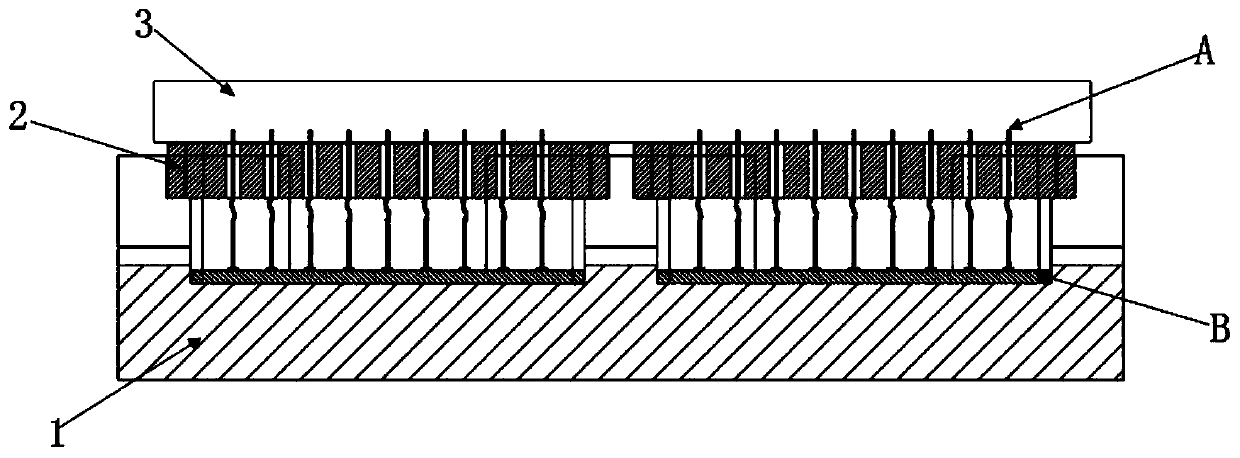
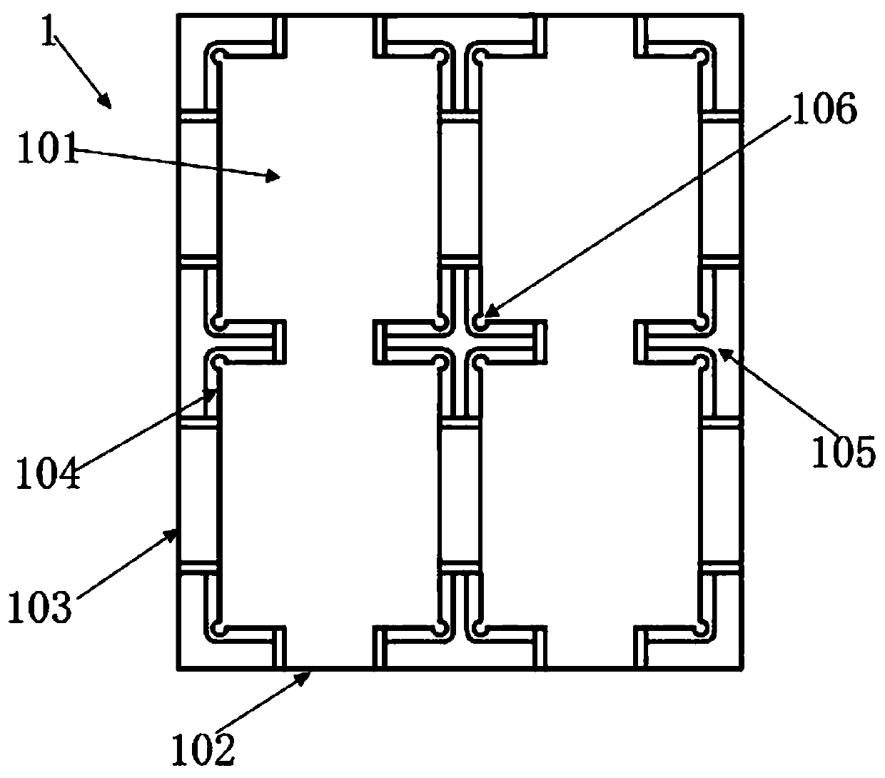
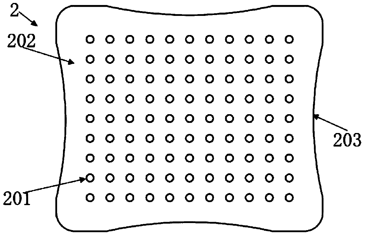
The invention relates to a pin welding fixture and a pin fixing method. A groove is formed in an upper end of a base portion; a gland portion is arranged on the upper portion of the base portion in afitted mode; a plurality of positioning holes penetrating up and down are formed on the gland portion; the positioning holes after the gland portion is fitted with the base portion cover over the groove; the gland portion is provided with an elastic body; the elastic body is used for fixing a pin according to the layout of the positioning holes; the elastic body carried with the fixed pin extendsinto the groove to make contact with a ceramic copper clad plate placed in the groove for welding, and the ceramic copper clad plate to be welded is pre-placed in a groove of a bottom plate body of the base portion; the ceramic copper clad plate is positioned through an inner positioning angle; the gland portion is placed upside down on the elastic body; the pin sequentially penetrates through thepositioning holes of the gland portion, so that the end of the pin is inserted into the elastic body; and the pin that is carried and fixed by the elastic body extends into the groove to contact theceramic copper clad plate placed in the groove, and the gland portion is fixed on the base portion by an external positioning angle. By means of the pin welding fixture and the pin fixing method, thewelding effect is good, and the welding is firm.

Description

technical field [0001] The invention relates to a pin welding tool and a pin fixing method, belonging to the technical field of welding processing. Background technique [0002] IGBT (Insulated Gate Bipolar Transistor), Insulated Gate Bipolar Transistor, is a composite full-control voltage-driven power semiconductor device composed of BJT (Bipolar Transistor) and MOS (Insulated Gate Field Effect Transistor). The pin plays the role of leading out the electrode signal in the IGBT package, so the welding strength and quality between the pin and the ceramic copper clad board DBC become an important indicator for evaluating the performance of the IGBT module. The pin soldering process is to print solder paste on the pad of the DBC substrate, then fix the pins, and finally enter the reflow furnace for soldering. The soldering quality can directly affect the heat dissipation and thermal fatigue resistance of the product. [0003] In the traditional technical solution, the good fix...

Claims


Application Information

Patent Timeline
Patent Type & Authority Applications(China)
IPC IPC(8): B23K3/08
CPCB23K3/08
Inventor 张茹臧天程安勇金浩王素隔
Owner YANTAI TAIXIN ELECTRONICS TECH CO LTD
Why Eureka
Try Eureka