
Cloth dyeing machine

A technology of dyeing machine and cloth storage tank, applied in the field of dyeing machine, can solve problems such as cloth damage, and achieve the effects of reducing damage, ensuring dyeing quality, and reducing self-rotation

Active Publication Date: 2019-05-10
HANGZHOU DONGLIN DYEING & FINISHING MACHINERY
View PDF7 Cites 4 Cited by
  • Summary
  • Abstract
  • Description
  • Claims
  • Application Information

AI Technical Summary

Problems solved by technology

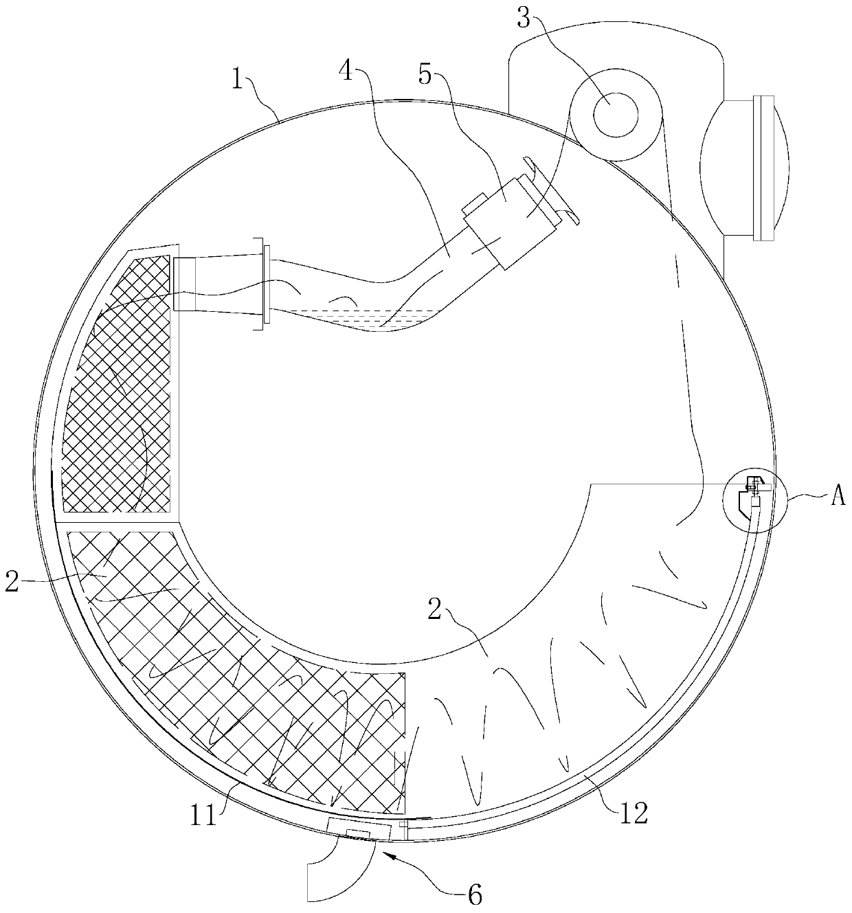
[0004] The above-mentioned existing technical solutions have the following defects: the nozzles are used to stamp the cloth and the left and right pipes are used to guide the cloth to be dyed repeatedly in the cylinder, but the existing left and right pipes and nozzles are all circular. When the nozzle impacts the cloth with water flow or air flow, since the inner wall of the left and right tube is circular, the water flow or air flow will flow in a vortex along the inner wall of the left and right tube, which may drive the cloth to wind along the inner wall of the left and right tube, causing the cloth to be subjected to torsion , causing cloth damage

Method used


Image

  • Cloth dyeing machine
  • Cloth dyeing machine
  • Cloth dyeing machine

Examples


Embodiment 2

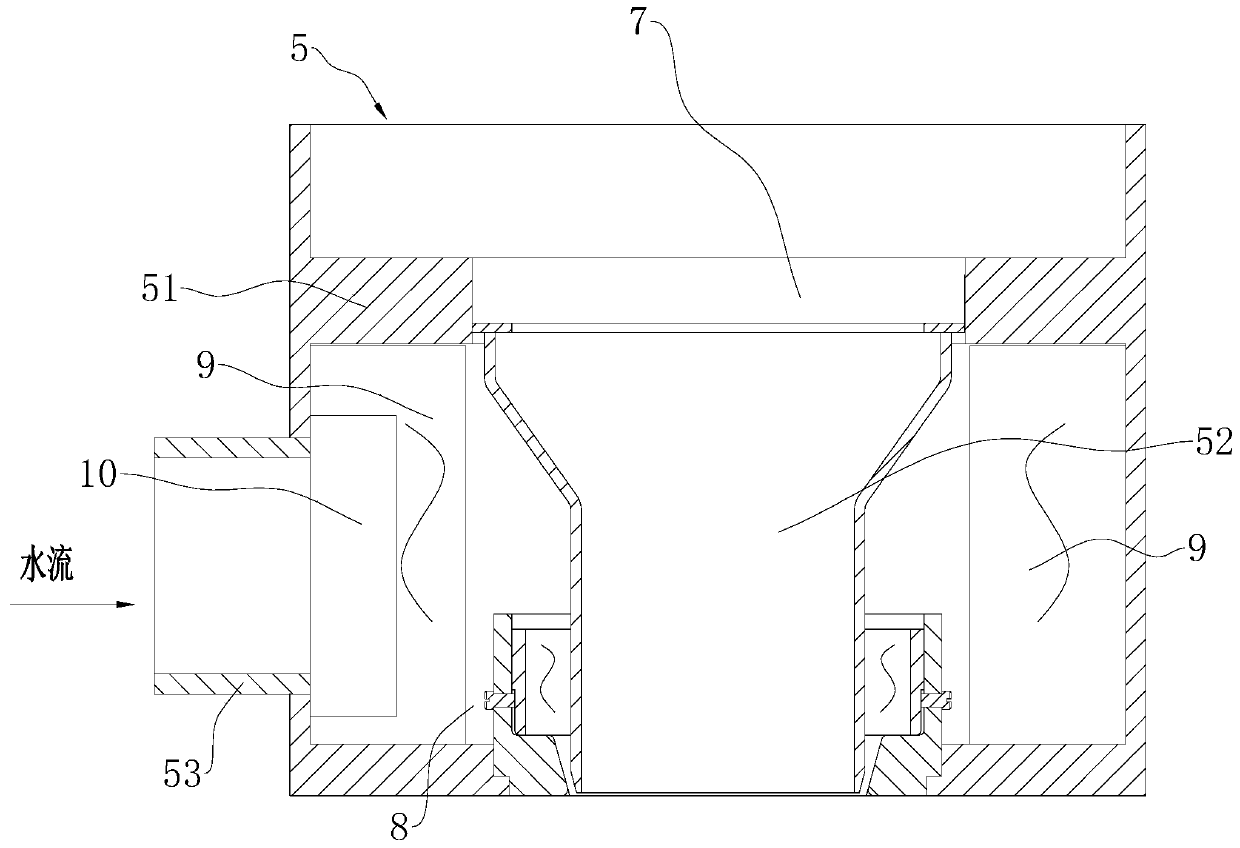
[0067] Embodiment 2: refer to Figure 11 The difference from Embodiment 1 is that the cylinder body 1 is externally connected with a heat exchanger 18, and the heat exchanger 18 communicates with the end of the liquid inlet pipe 53 opposite to the seat body 51, and the heat exchanger 18 is also connected with a liquid inlet pipe 23, The liquid inlet pipe 23 is connected with two water inlet pipes 22 and the drain pipe 61. The two water inlet pipes 22 and the drain pipe 61 are respectively provided with valves 21. The liquid inlet pipe is located at a section between the heat exchanger 18 and the water inlet pipe 22. A water pump 20 and a filter 19 are arranged on it; the valve 21 on the water inlet pipe 22 and the drain pipe 61 can be used to control the opening and closing of the corresponding pipe, thereby controlling the flow of water entering the heat exchanger 18, and at the same time, the cylinder 1 can be discharged After heat exchange, the water flow continues to pass ...


PUM


Abstract

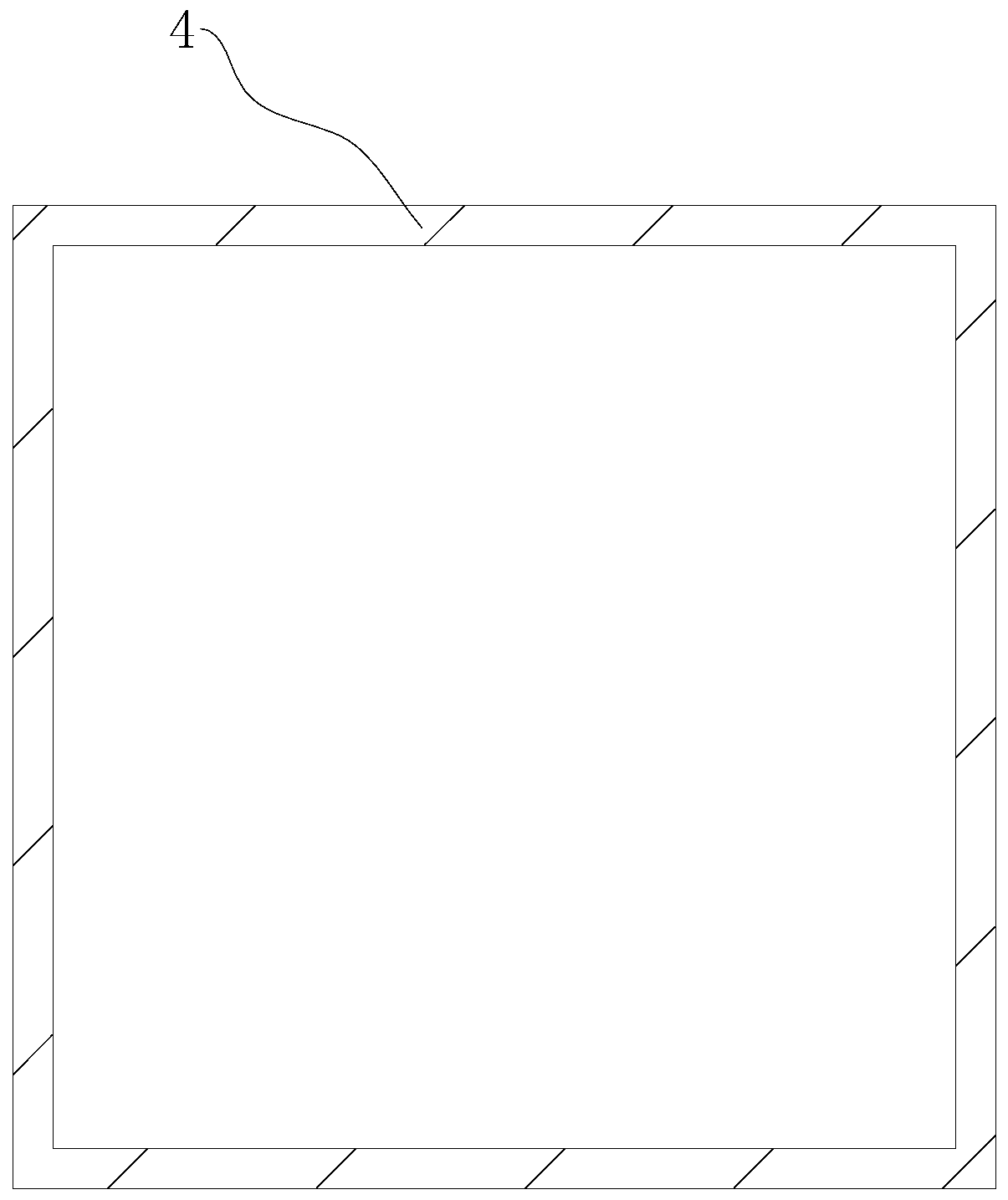
The invention relates to a cloth dyeing machine comprising a cylinder body, a cloth storage trough arranged in the cylinder body, a cloth lifting device, a nozzle, a cloth layout pipe and a water collecting device; one end of the cloth layout pipe is in communication with one end of the cloth storage trough; the cloth layout pipe is bent and is arranged in a V shape with an upward opening, the bent part of the cloth layout pipe is arranged to be a circular arc, and the section of the cloth layout pipe is arranged to be polygonal; and the nozzle comprises a seat body and a nozzle core, the seatbody is coaxially fixed with the cloth layout pipe, a placing channel for placing the nozzle core is formed inside the seat body, the side wall of the seat body is in communication with a liquid inlet pipe, an annular groove in communication with the liquid inlet pipe and the placing channel is formed along the circumference in the seat body, and a plurality of rotation preventing plates I are uniformly arranged along the circumference in the annular groove. The cloth dyeing machine has the effects of reducing cloth damage and guaranteeing the quality of the cloth by reducing overturning andtwisting probability in a cloth conveying process.

Description

technical field [0001] The invention relates to the technical field of cloth dyeing equipment, in particular to a cloth dyeing machine. Background technique [0002] At present, in the dyeing industry of light industry textile dyeing and finishing, the dyeing machine is one of the main equipments for the production of finished cloth. . [0003] The existing Chinese patent with the authorized notification number CN104452137B discloses a cloth dyeing machine with fast leveling function, including a cylinder body, a cloth lifting device, a first cloth conveying pipe, a second cloth conveying pipe and a left and right pipe; the cylinder body There is a cloth storage tank inside, the distribution pipe is located in the cylinder body, the cloth inlet end of the distribution pipe is connected with the first cloth outlet end of the distribution pipe, the first distribution pipe passes through the top of the cylinder body, and the first distribution pipe The cloth inlet end of the ...

Claims


Application Information

Patent Timeline
Patent Type & Authority Applications(China)
IPC IPC(8): D06B3/28D06B23/20
Inventor 陈信宏杨年杰刘泰维
Owner HANGZHOU DONGLIN DYEING & FINISHING MACHINERY
Learn More