Automatic assembling and disassembling drill rod for mining drilling machine, water feeder unit, device and construction method

An automatic loading and unloading and water feeder technology, which is applied in the direction of drill pipes, drill pipes, drilling equipment, etc., can solve the problems of low drilling efficiency, low loading and unloading efficiency, etc., and achieve the goal of improving drilling efficiency, improving construction efficiency, and safe and reliable connection Effect

Active Publication Date: 2019-05-10
XIAN RES INST OF CHINA COAL TECH& ENG GROUP CORP
View PDF18 Cites 10 Cited by
  • Summary
  • Abstract
  • Description
  • Claims
  • Application Information

AI Technical Summary

Problems solved by technology

[0003] Aiming at the defects and deficiencies in the prior art, the present invention provides a unit, device and construction method for automatically loading and unloading the drill pipe and the

Method used


Image

  • Automatic assembling and disassembling drill rod for mining drilling machine, water feeder unit, device and construction method
  • Automatic assembling and disassembling drill rod for mining drilling machine, water feeder unit, device and construction method
  • Automatic assembling and disassembling drill rod for mining drilling machine, water feeder unit, device and construction method

Examples


Embodiment 1

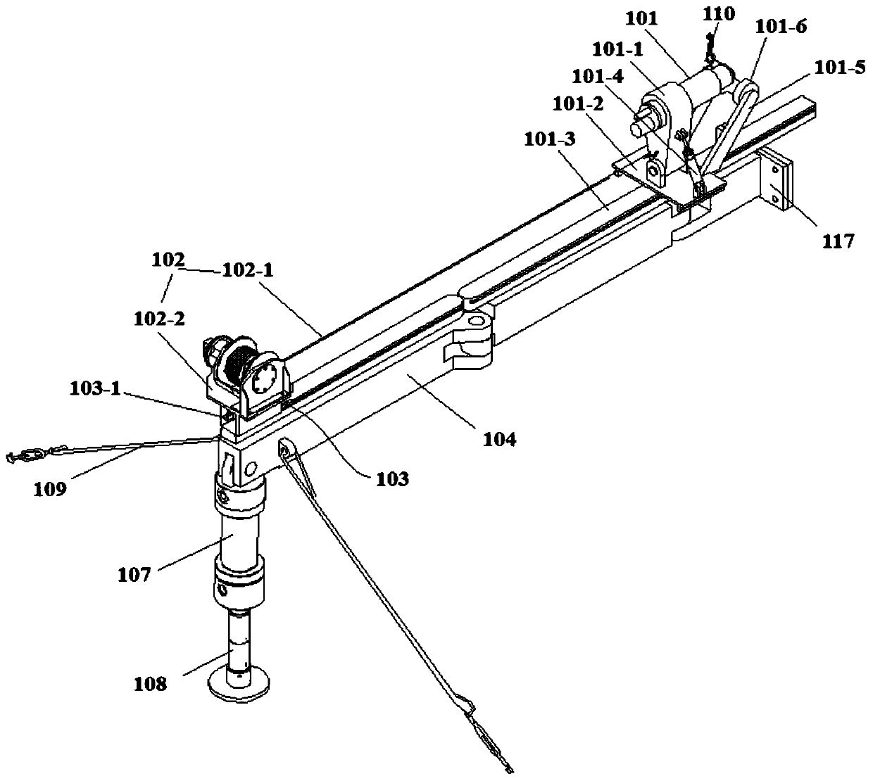
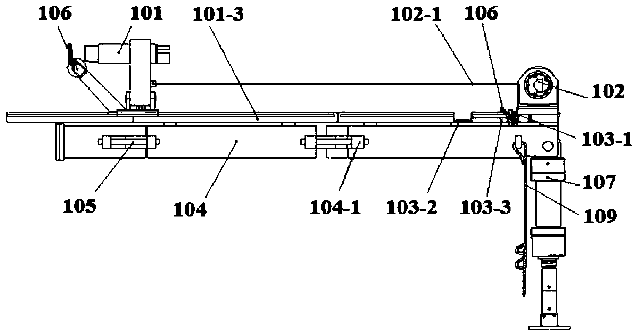
[0064] Such as Figures 1 to 5 As shown, the present embodiment provides a mining rig for automatically loading and unloading drill pipes and a water feeder unit, including a water feeder bracket 101-1, a hydraulic winch 102 connected to the water feeder bracket 101-1 to pull the water feeder bracket 101-1 to The water feeder 101 is separated from the drill pipe and the pushing unit 103 between the water feeder bracket 101-1 and the hydraulic winch 102 is used to push the water feeder bracket 101-1 so that the water feeder 101 is connected to the drill pipe; the water feeder bracket 101-1 passes through the moving plate 101-2 is movably installed on the guide rail 101-3 of the water feeder, and the guide rail 101-3 of the water feeder is set on the guide rail bracket 104; the hydraulic winch 102 is installed on the guide rail bracket 104, and the wire rope 102-1 of the hydraulic winch 102 is connected to the water feeder bracket 101-1; the pushing unit 103 is arranged on the g...

Embodiment 2

[0074] Such as Figures 6 to 8 As shown, this embodiment provides a water feeder that can be used in Embodiment 1. The water feeder includes a mandrel 1, a bearing 2 and a bearing sleeve 3 arranged coaxially from the inside to the outside in sequence, and on the side of the mandrel 1 A high-pressure water interface 4 is installed on the wall; it also includes a force transmission hollow shaft 5 with one end closed and the other end open, which is coaxially tightly fitted in the mandrel 1 and can move axially; the high-pressure water interface 4 is sealed and communicated with the force transmission hollow shaft 5 , to pass high-pressure water into the power transmission hollow shaft 5; the closed end of the power transmission hollow shaft 5 is provided with a hydraulic piston, and the open end of the power transmission hollow shaft 5 is flush with the other end of the mandrel 1 and is equipped with a The core rod 10 that moves axially with the force transmission hollow shaft 5...

Embodiment 3

[0081] This embodiment also provides a construction method for the water feeder in the above embodiments, including the following steps:

[0082] Step 1: Push the force transmission hollow shaft to move axially through the hydraulic piston, and push the core rod, annular piston and claws to move axially, so that the second spring and the third spring are compressed, and the moving speed of the core rod is faster than that of the claws The speed makes the wedge-shaped outer wall of the piston block away from the wedge-shaped surface of the claw, the first spring resets, the claw shrinks, and the elastic piece of the claw is inserted into the internal thread of the drill pipe;

[0083] Step 2: Loosen the hydraulic piston again. Under the reset action of the second spring and the third spring, the elastic sheet, annular piston, core rod and force transmission hollow axis move in the direction of the hydraulic piston. During the movement of the elastic sheet, the wedge-shaped outer...


PUM


Abstract

The invention discloses an automatic assembling and disassembling drill rod for a mining drilling machine, a water feeder unit, a device and a construction method. Included are a water feeder support,a hydraulic winch connected with the water feeder support to pull the water feeder support to separate a water feeder from a drill rod, and a pushing unit located between the water feeder support andthe hydraulic winch to push the water feeder support to enable the water feeder to be connected with the drill rod. The water feeder support is movably installed on a water feeder guide rail througha movable plate; and the water feeder guide rail is arranged on a guide rail support. The hydraulic winch is mounted on a guide rail support; a steel wire rope of the hydraulic winch is connected withthe water feeder support; and a pushing unit is arranged on the guide rail support between the water feeder guide rail and the hydraulic winch, and can push the water feeder support to move along thewater feeder guide rail. The technical problems of a power head rear rod adding mode and automatic assembling and disassembling of a medium drill rod and long drill rod in a coal mine underground directional drilling process are solved, instant assembly and disassembly of the water feeder and the drill rod can be achieved, and the drilling efficiency can be effectively improved.

Description

technical field [0001] The invention belongs to the technical field of underground directional drilling rigs in coal mines, and in particular relates to an automatic loading and unloading drill pipe and water feeder unit, device and construction method of a mining drilling rig. Background technique [0002] In the process of directional drilling in coal mines, it is necessary to frequently load and unload drill pipes to complete drilling construction and deal with stuck and buried drill accidents. At present, directional drilling rigs generally adopt the method of adding rods behind the power head. During the process of adding drill pipes, frequent loading and unloading of water feeders is required, and manual operations are required, which is labor-intensive for workers. For non-directional drilling rigs, the method of adding rods between the gripper and the power head (during the drilling operation, only the drilling rods need to be loaded and unloaded, and the water feede...

Claims


Application Information

Patent Timeline
IPC IPC(8): E21B19/14E21B19/16E21B7/04
Inventor 陈彦宇田东庄孙保山刘庆修吕孟杨瑞博许翠华路前海高勇刘欢
Owner XIAN RES INST OF CHINA COAL TECH& ENG GROUP CORP
Why Eureka
Try Eureka