
COT control-based internal ripple compensation circuit and control method thereof

A control circuit, ripple compensation technology, applied in the control/regulation system, electrical components, regulating electrical variables, etc., can solve the problems of reducing market competitiveness, increasing the complexity and cost of the control system, and the compensation effect cannot be optimized.

Pending Publication Date: 2019-05-10
QX MICRO DEVICES
View PDF0 Cites 4 Cited by
  • Summary
  • Abstract
  • Description
  • Claims
  • Application Information

AI Technical Summary

Problems solved by technology

It can be seen that the traditional compensation method often needs to use additional external components to achieve compensation, which increases the complexity and cost of the entire control system
[0004] The disadvantage of the traditional technology is: due to the use of external discrete components to achieve ripple compensation, the ripple compensation parameters are affected by changes in peripheral components, the compensation effect cannot be optimal, and the complexity and cost of the entire system are increased. reduce market competitiveness

Method used


Image

  • COT control-based internal ripple compensation circuit and control method thereof
  • COT control-based internal ripple compensation circuit and control method thereof
  • COT control-based internal ripple compensation circuit and control method thereof

Examples


Embodiment Construction

[0053] The present invention will be described in further detail below in conjunction with accompanying drawing:

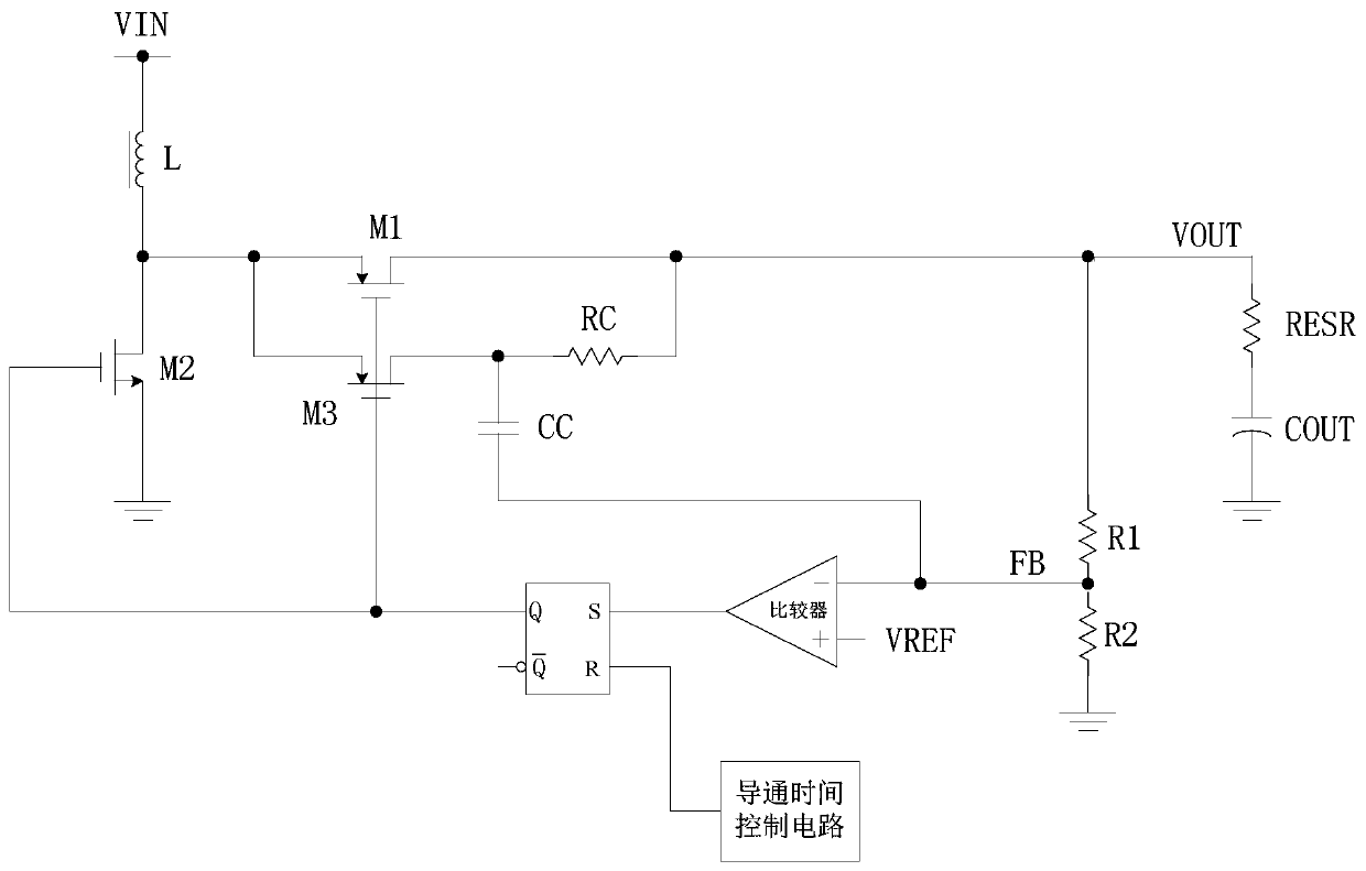
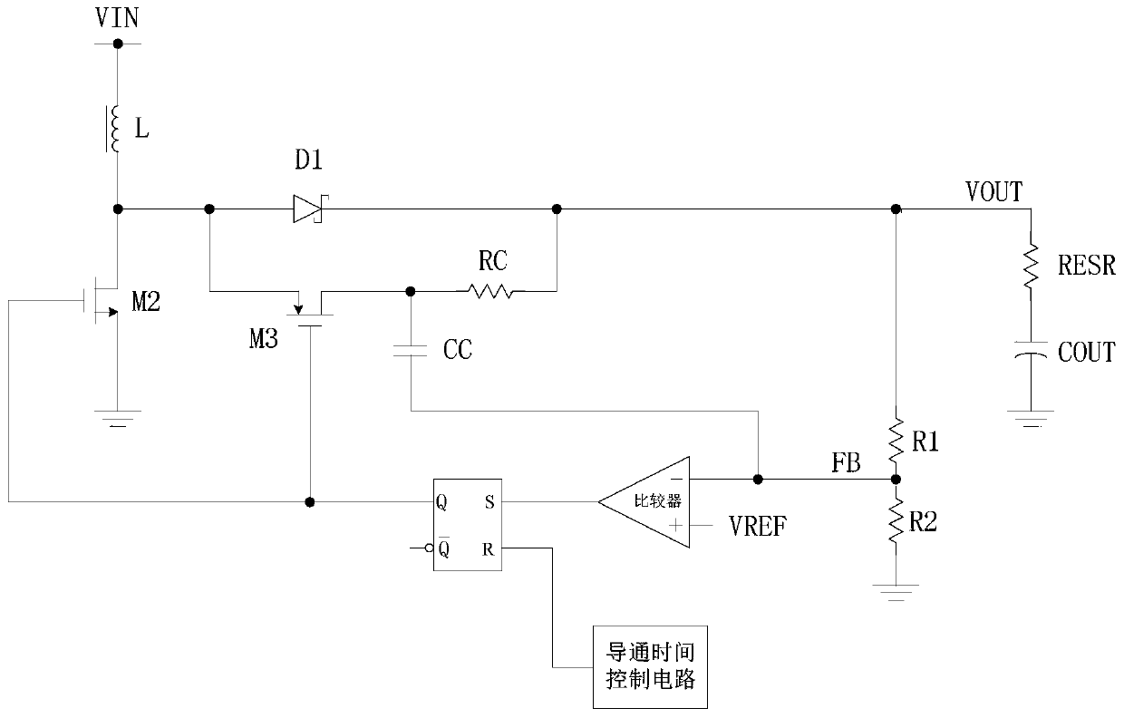
[0054] The first technical solution of the present invention is the internal ripple compensation circuit of the boost converter based on COT control, including: voltage input terminal, power tube, rectifier tube, inductor, comparator, on-time control circuit, Resistor, RS flip-flop, compensation capacitor, output capacitor; the divided voltage of the output terminal voltage acts on the comparator as a feedback voltage, and the feedback voltage is compared with the reference voltage of the comparator; the output signal obtained by the comparator acts on the RS flip-flop for Control the conduction of the power tube or the conduction of the rectifier tube; when the output terminal voltage is lower than the preset voltage, the feedback voltage is lower than the reference voltage, the power tube is turned on, the rectifier tube is cut off, the inductor stores energy, an...


PUM


Abstract

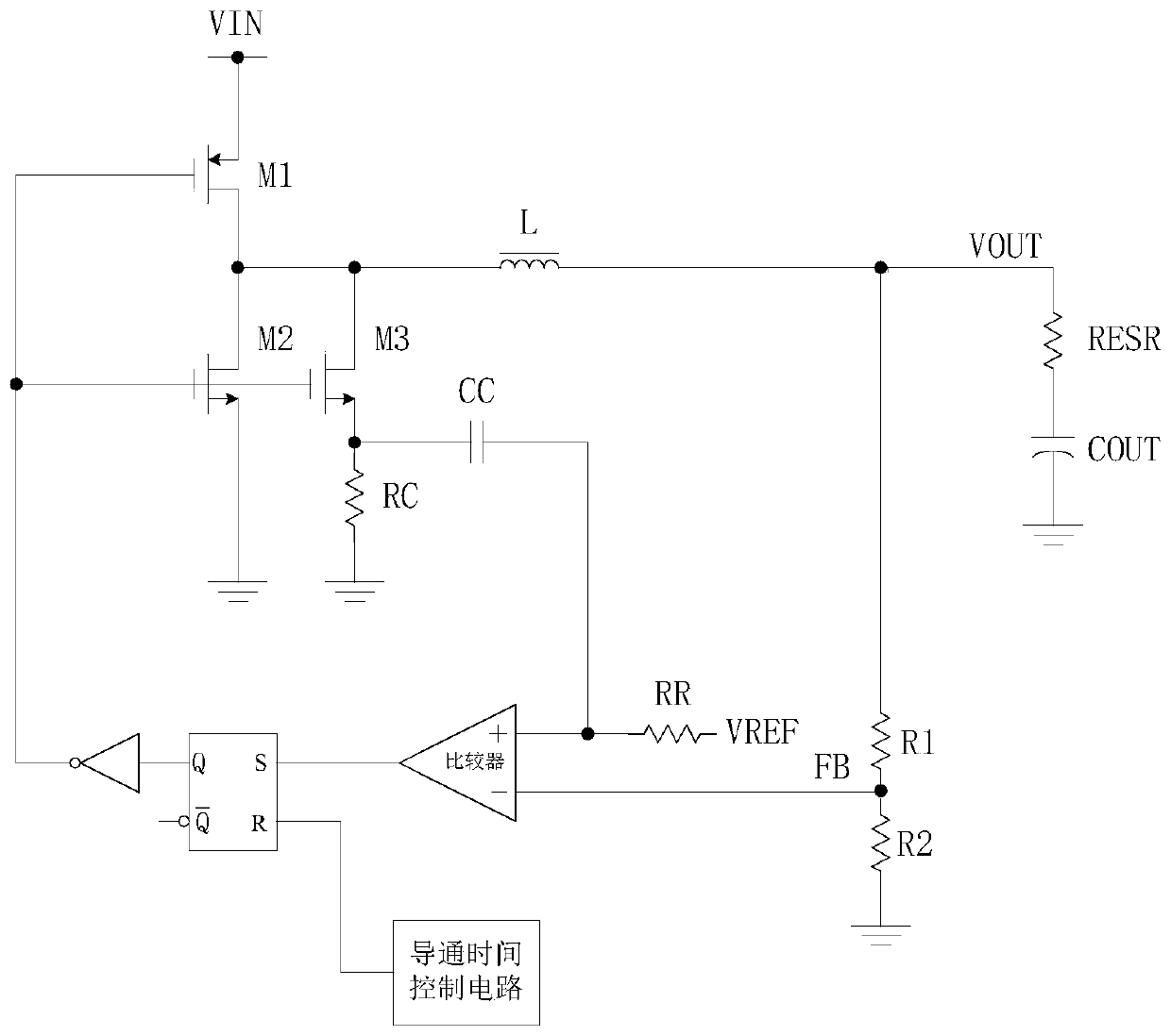
The invention relates to a COT control-based internal ripple compensation circuit and a control method thereof. A division voltage of an output end voltage of the circuit is used as a feedback voltagefor being acted on a comparator, the feedback voltage is compared with a reference voltage of the comparator, an output signal obtained by the comparator is acted on a RS trigger to control conduction of a power tube or a rectification tube, the power tube is conducted, the rectification tube is cut off and energy is stored in an inductor when the output end voltage is lower than a preset voltageand the feedback voltage is lower than the reference voltage, a conduction time control circuit starts to time, the RS trigger is controlled by the conduction time control circuit after preset time is reached, so that the power tube is cut off, the rectification tube is conducted, energy is released to an output capacitor from the inductor, the ripple compensation circuit generates a ripple voltage, the feedback voltage is larger than the reference voltage by the ripple voltage, and subharmonic oscillation of the circuit caused by excessively small series resistance of the output capacitor isprevented.

Description

technical field [0001] The invention relates to the field of power supplies, in particular to an internal ripple compensation circuit based on COT control and a control method thereof. Background technique [0002] With the rapid development of electronic technology, the power supply, which is the heart of the electronic system, has also made unprecedented progress. Switching power supply and linear power supply are two main aspects of the development of modern electronic power supply. Switching power supply is widely used in various terminal equipment, communication equipment and other electronic equipment dominated by electronic computers due to its small size, light weight and high efficiency. With the higher and higher requirements for switching power supplies, the research on control circuits has become a focus of attention. In order to ensure the efficient and reliable operation of electronic equipment, its power supply needs to have high light-load efficiency and fas...

Claims


Application Information

Patent Timeline
IPC IPC(8): H02M3/158H02M1/14
Inventor 吴玉强黄朝刚陈美玲李剑毛晓峰
Owner QX MICRO DEVICES
Learn More