Supercharge Your Innovation With Domain-Expert AI Agents!

Power improvement method for inductive electric power transmission system

A technology of inductive power transmission and power, applied in output power conversion devices, control/regulation systems, conversion of AC power input to DC power output, etc. The effect of increasing the transmission power

Active Publication Date: 2019-05-10
INST OF ELECTRICAL ENG CHINESE ACAD OF SCI +1
View PDF2 Cites 0 Cited by
  • Summary
  • Abstract
  • Description
  • Claims
  • Application Information

AI Technical Summary

Problems solved by technology

For occasions where the input DC voltage and the output DC voltage are fixed, the voltage obtained by the load is required to be fixed. If the switching frequency is set equal to the resonant frequency of the primary coil: f sw =f pr , a part of the output voltage of the secondary converter is used to provide the reactive power of the secondary circuit. When the output voltage of the secondary converter reaches the maximum value, the output voltage of the primary converter does not reach the maximum value, resulting in The transmission power of the system drops
[0012] To sum up, when the input DC voltage and output DC voltage are fixed, when the resonant frequencies of the primary and secondary coils and their respective compensation capacitors are not exactly the same, how to set the switching frequency so that the efficiency of the non-contact transformer is the highest and the load obtained Maximum power is a problem in system debugging, which has not been reported in the existing literature

Method used


Image

  • Power improvement method for inductive electric power transmission system
  • Power improvement method for inductive electric power transmission system
  • Power improvement method for inductive electric power transmission system

Examples


Embodiment Construction

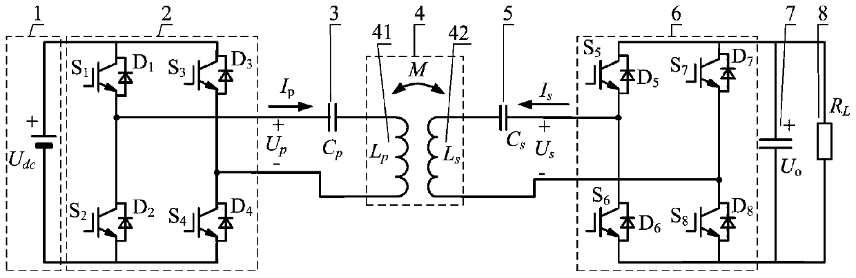
[0057] figure 2 Shown is the basic structure of the series compensation inductive power transmission system of the embodiment of the present invention. Such as figure 2 As shown, the series compensation inductive power transmission system of the embodiment of the present invention includes a DC power supply 1, a primary side converter 2, a primary side coil compensation capacitor 3, a non-contact transformer 4, a secondary side coil compensation capacitor 5, and a secondary side converter 6, filter capacitor 7, and load 8.

[0058]The output end of the DC power supply 1 is connected to the input end of the primary converter 2; one end of the output terminal of the primary converter 2 is connected to one end of the primary coil 41 of the non-contact transformer, and the other end of the output terminal of the primary converter 2 Connect with one end of the non-contact transformer primary coil compensation capacitor 3, the other end of the non-contact transformer primary coi...


PUM


Abstract

The invention discloses a power improvement method for an inductive electric power transmission system. The inductive electric power transmission system comprises a primary side high-frequency inversion device, a primary side transmitting coil, a secondary side receiving coil and a secondary side rectification device and is characterized in that the switching frequency of a current transformer isarranged on a specific frequency point between the respective resonant frequency of the primary side coil and the respective resonant frequency of the secondary side coil when the resonant frequency of the primary side transmitting coil and the resonant frequency of the secondary side receiving coil are not consistent, then, a secondary side current transformer is subjected to load impedance transformation, and transmission power between the primary side and the secondary side of the inductive electric power transmission system can be improved.

Description

technical field [0001] The invention relates to a power boosting method of an inductive electric energy transmission system. Background technique [0002] Inductive power transfer (IPT) technology has gradually entered the field of industry and life, and its application in electric vehicle charging and rail transit vehicle power supply is the future development trend. Existing rail transit vehicles mostly use pantograph or third rail for power supply. When the rail transit vehicle is running, the friction of the pantograph or the third rail is likely to produce carbon deposits, resulting in poor contact, and the vehicle is disconnected from the grid, which reduces the reliability of the power supply system and affects the service life of the vehicle power supply system equipment. Bows or third rails require high maintenance costs. The inductive power transmission using the principle of electromagnetic induction realizes the non-contact transmission of power, solves the pro...

Claims


Application Information

Patent Timeline
Patent Type & Authority Applications(China)
IPC IPC(8): H02M3/335H02J50/12H02M7/00
CPCY02B70/10
Inventor 史黎明姜龙斌殷正刚唐立国潘硕
Owner INST OF ELECTRICAL ENG CHINESE ACAD OF SCI
Features
  • R&D
  • Intellectual Property
  • Life Sciences
  • Materials
  • Tech Scout
  • Unparalleled Data Quality
  • Higher Quality Content
  • 60% Fewer Hallucinations
Learn More