Outlet energy dissipation arrangement structure for centralized arrangement of different water release structures on shore of hydroelectric project

A technology for drainage structures and hydropower projects, applied in water conservancy projects, buildings, sea area projects, etc., can solve problems such as different discharge volumes, rapid deflection energy dissipation, and insufficiency, so as to avoid secondary energy dissipation and save engineering investment , the effect of increasing flexibility and reliability

Pending Publication Date: 2019-05-14
POWERCHINA BEIJING ENG
View PDF0 Cites 3 Cited by
  • Summary
  • Abstract
  • Description
  • Claims
  • Application Information

AI Technical Summary

Problems solved by technology

[0004] The technical problem to be solved by the present invention is to provide an outlet energy dissipation layout structure for centralized arrangement of different discharge structures on the bank of a hydropower project, so as to solve the deflection and insufficient energy dissipation of jet streams with different discharge volumes and different entry angles.

Method used


Image

  • Outlet energy dissipation arrangement structure for centralized arrangement of different water release structures on shore of hydroelectric project
  • Outlet energy dissipation arrangement structure for centralized arrangement of different water release structures on shore of hydroelectric project
  • Outlet energy dissipation arrangement structure for centralized arrangement of different water release structures on shore of hydroelectric project

Examples


Embodiment Construction

[0018] Below in conjunction with accompanying drawing and specific embodiment the present invention is described in further detail:

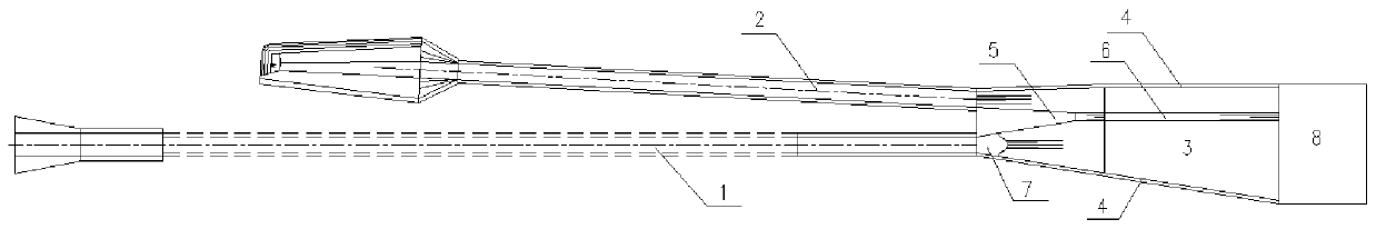
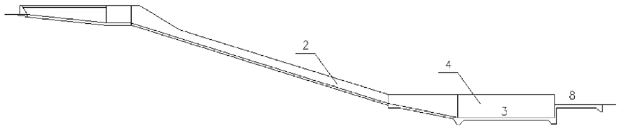
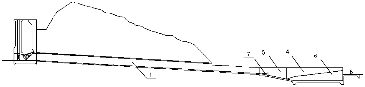
[0019] Such as Figure 1-5 As shown, the outlet energy dissipation layout structure of the different discharge structures on the bank of the hydropower project of the present invention includes a spillway 1, a spillway 2, a stilling basin 3 and auxiliary energy dissipation facilities, the axis of the spillway 1 and the spillway 2 The angle between the axes is small, and the outlets of the two share a stilling basin 3 for energy dissipation. The stilling basin 3 and auxiliary energy dissipation facilities are located downstream of the outlet of the spillway and the spillway, and the stilling basin 3 is surrounded by side walls 4 on both sides. It is formed in an asymmetric trumpet-shaped arrangement on the plane, and the bottom is composed of a slope transition section and a horizontal section. The apron 8 downstream of the force pool 3; the div...


PUM


Abstract

The invention discloses an outlet energy dissipation arrangement structure for centralized arrangement of different water release structures on the shore of a hydroelectric project. The included anglebetween the axis of a flood discharge tunnel and the axis of a spillway is small, the outlet portions of the flood discharge tunnel and the spillway share one stilling pool for energy dissipation, the stilling pool is arranged in an asymmetric horn shape on a plane, the bottom of the stilling pool is composed of a slope transition section and a horizontal section, and the auxiliary energy dissipation facility comprises a diversion pier, a submerged middle partition wall, a waveform reverse arc small flip bucket and an apron. The diversion pier is positioned on the slope transition section ofthe stilling pool, and the initial end of the diversion pier is positioned in the middle of the flood discharge tunnel outlet and the spillway outlet and is a widened equal-top-elevation isolation wall, and the submerged middle partition wall is located at the downstream of the diversion pier and is a variable-top-elevation partition wall with equal width and gradually increased height, and the stilling pool is divided into a left part and a right part by the diversion pier and the submerged middle partition wall. The waveform reverse arc small flip bucket is located at the slope transition section of the stilling pool. According to the outlet energy dissipation arrangement structure, the problems that when a same asymmetric energy dissipation pool is adopted for centralized energy dissipation at different flood discharge building outlets, rotation and energy dissipation of high-speed asymmetric water flow are not sufficient are solved, and engineering investment is saved.

Description

technical field [0001] The invention relates to an energy-dissipating arrangement type of discharge structures of a hydropower project, in particular to an outlet energy-dissipating arrangement structure when different discharge structures are collectively arranged on the bank of a shore hydropower project. Background technique [0002] The drainage structures on the shore of hydropower projects have different discharge distributions, and energy dissipation is often arranged in scattered areas to reduce the impact of erosion and atomization. Restricted by topographical and geological conditions, the shore discharge structures of some projects, such as spillway tunnels and spillways, will be arranged in a centralized manner and the energy dissipation at the outlet will be arranged in a centralized manner. In order to reduce the problem of erosion and atomization, the energy dissipation method at the outlet will The energy dissipation of the pool is mainly used; due to the dif...

Claims


Application Information

Patent Timeline
Patent Type & Authority Applications(China)
IPC IPC(8): E02B8/06
Inventor 孔彩粉杨文利李冰张续沈加旺
Owner POWERCHINA BEIJING ENG
Why Eureka
Try Eureka