Ultrasonic transducer array structure and manufacturing method thereof

An ultrasonic transducer and array structure technology, which is applied in ultrasonic/acoustic/infrasonic diagnosis, acoustic diagnosis, infrasonic diagnosis, etc., can solve the problems of reduced image resolution, large data volume, unfavorable image processing, etc., to reduce diagnosis time , high operating frequency, and improved resolution

Active Publication Date: 2020-11-13
INST OF MICROELECTRONICS CHINESE ACAD OF SCI
View PDF7 Cites 0 Cited by
  • Summary
  • Abstract
  • Description
  • Claims
  • Application Information

AI Technical Summary

Problems solved by technology

Currently, the one-dimensional linear array transducers used in the medical field can only obtain three-dimensional images through scanning and reconstruction. Image reconstruction is performed, so the detection time is long and the amount of data is huge, which is not conducive to image processing; second, the scanned data is obtained in different time periods, so real-time information of living tissues cannot be obtained; third, due to the large amount of scanning data , the acquired data are not in the same time period, and because the resolution of the ultrasonic transducer probe itself is not high, the image resolution will be further reduced after image reconstruction
The main problem of these methods is that when the number of transducer array elements increases and the unit size is further reduced, it is difficult to make interconnection lines and the placement accuracy is difficult to control.
Therefore, the current packaging and interconnection methods of ultrasonic transducer arrays cannot meet the needs of high density, high frequency, light weight and small volume of ultrasonic transducers in the medical field in the future.

Method used


Image

  • Ultrasonic transducer array structure and manufacturing method thereof
  • Ultrasonic transducer array structure and manufacturing method thereof
  • Ultrasonic transducer array structure and manufacturing method thereof

Examples


Embodiment Construction

[0047] In order to make the purpose, technical solutions and advantages of the embodiments of the present invention clearer, the technical solutions of the present invention will be clearly and completely described below in conjunction with the accompanying drawings. Obviously, the described embodiments are part of the embodiments of the present invention, not all of them. the embodiment. Based on the embodiments of the present invention, all other embodiments obtained by persons of ordinary skill in the art without making creative efforts belong to the protection scope of the present invention.

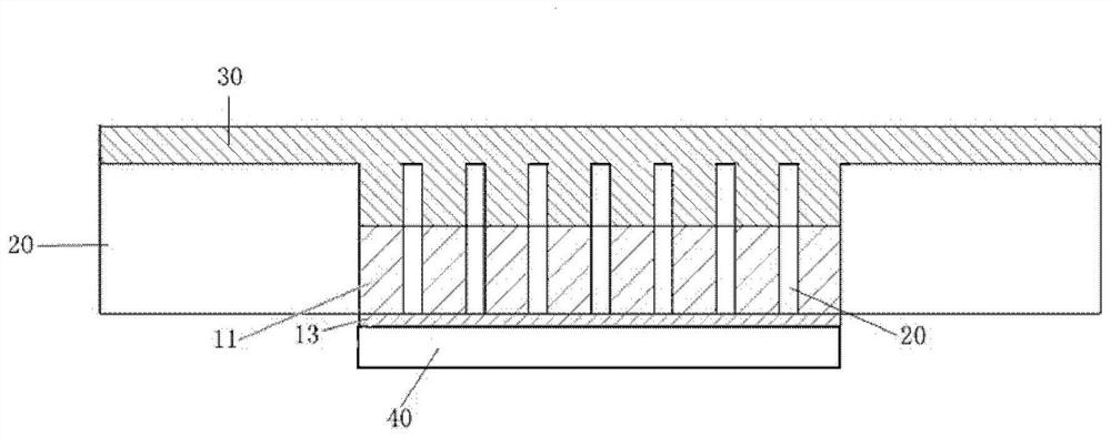
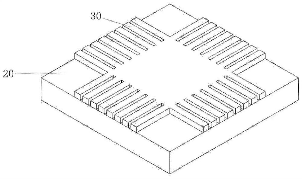
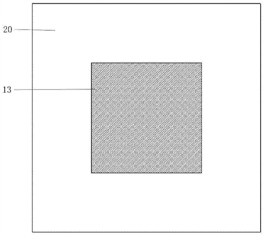
[0048] The ultrasonic transducer array structure and its preparation method provided by the embodiment of the present invention can solve the problem that the high frequency and high density of the ultrasonic transducer cannot be satisfied at the same time in the prior art; it can greatly improve the performance of the medical ultrasonic transducer operating frequency, reducing devic...


PUM


Abstract

The invention provides an ultrasonic transducer array structure and a preparation method thereof, and belongs to the technical field of medical equipment. The ultrasonic transducer array structure comprises an ultrasonic transducer array body, glue, a metal interconnect layer and an acoustic matching layer; the metal interconnect layer covers the surface of the glue and the ultrasonic transducer array body; the surfaces of the glue and the ultrasonic transducer array body are covered with the metal interconnect layer; the ultrasonic transducer array body is embedded in the glue; and the lowerpart of the ultrasonic transducer array body is covered with the acoustic matching layer. The ultrasonic transducer array structure realizes the demand for high density, high frequency, light weight and small volume of the ultrasonic transducer in the medical field.

Description

technical field [0001] The invention relates to the technical field of medical equipment, in particular to an array structure of an ultrasonic transducer and a preparation method thereof. Background technique [0002] As a non-invasive, painless, convenient, intuitive and effective inspection method, ultrasonic diagnosis has been widely used in the medical field. The main device for generating ultrasonic waves is the ultrasonic transducer. The ultrasonic transducer array structure currently used in the medical field is mainly used in in vitro examinations, such as abdominal B-ultrasound. The working frequency of the in vivo ultrasonic transducer probe composed of an ultrasonic transducer array structure is generally not high, so the resolution is not high, and the probe size is large, and the patient is prone to discomfort during diagnosis, which makes the patient afraid of the diagnostic process And uneasy. The main problems that limit the miniaturization and image clari...

Claims


Application Information

Patent Timeline
Patent Type & Authority Patents(China)
IPC IPC(8): B06B1/02A61B8/00
Inventor 鲁瑶万里兮
Owner INST OF MICROELECTRONICS CHINESE ACAD OF SCI
Why Eureka
Try Eureka