Ice cream stick feeding device
An ice cream stick, feeding and mixing technology, applied in the field of ice cream stick feeding device, can solve the problems of unfavorable recycling and reuse of ice cream sticks, lack of cleaning function, etc., and achieve the effect of facilitating recycling, improving convenience and improving elasticity
- Summary
- Abstract
- Description
- Claims
- Application Information
AI Technical Summary
Problems solved by technology
Method used
Image
Examples
Embodiment 1
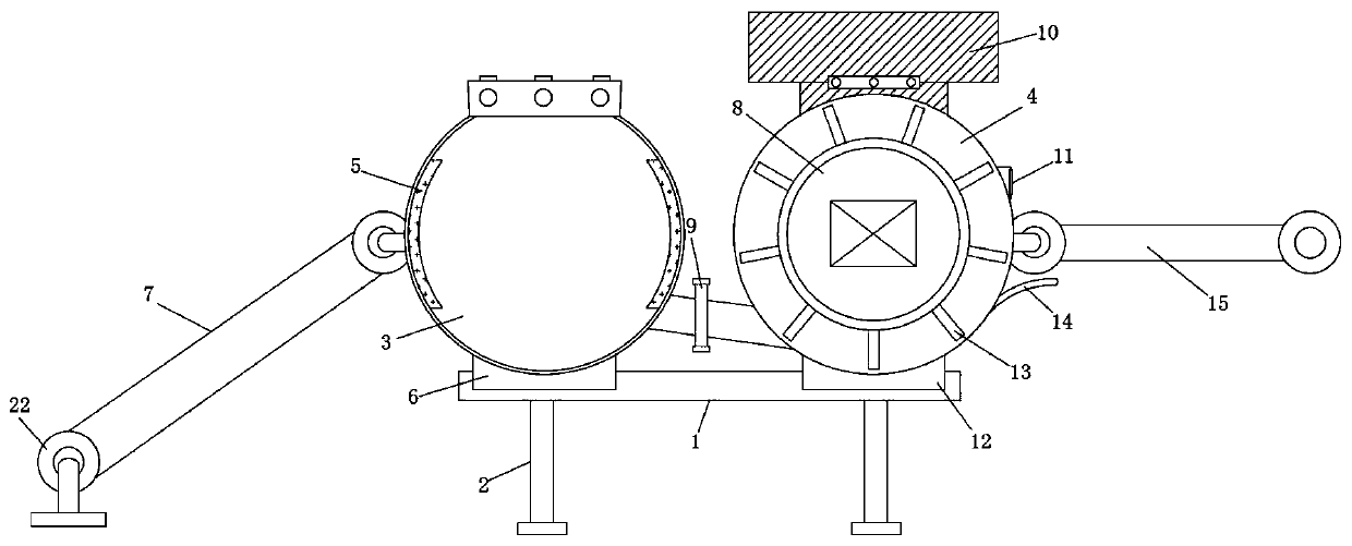
[0025] like figure 1 As shown, an ice cream stick feeding device includes a base 1 and a support frame 2, the bottom of the base 1 is fixedly connected to the support frame 2, an ultrasonic cleaning machine 3 is installed on one side of the upper part of the base 1, and a circular cleaning machine is installed on the other side of the upper part of the base 1. Shaped case 4, one side of the ultrasonic cleaning machine 3 is inlaid with a connecting valve 9, the ultrasonic cleaning machine 3 is connected to the circular case 4 through the connecting valve 9, both sides of the inner wall of the ultrasonic cleaning machine 3 are inlaid with germicidal lamps 5, and the upper part of the circular case 4 An air dryer 10 is installed.
[0026] In this embodiment, by setting the ultrasonic cleaner 3 and the air dryer 4, the ice cream sticks can be effectively cleaned during the feeding process, and the cleaned ice cream sticks can be air-dried.
Embodiment 2
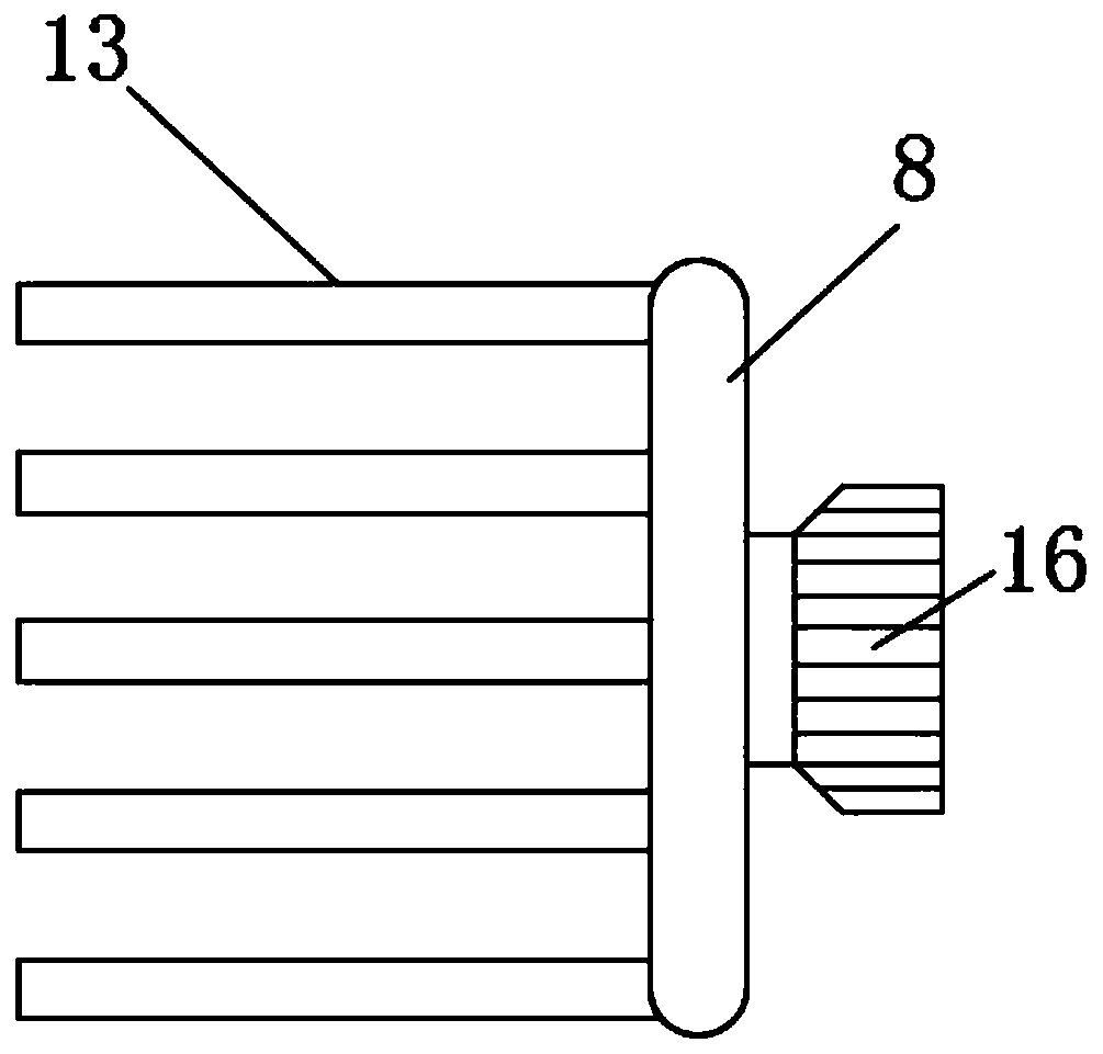
[0028] like Figure 1-4 As shown, the inside of the circular cabinet 4 is provided with a feeding stirring plate 13, a rotating disc 8 is installed on one side of the circular cabinet 4, and a feeding stirring plate 13 is arranged around the rotating disc 8, and a motor-16 is installed on the outer side of the feeding stirring plate 13. , the output shaft of motor one 16 is clamped with the feeding stirring plate 13, a conveyor belt one 7 is installed on one side of the ultrasonic cleaning machine 3, a rotating wheel 22 is installed at both ends of the conveyor belt one 7, and a motor two 23 is arranged on the outer side of the rotating wheel 22, The output shaft of the motor two 23 is connected with the rotating wheel 22, and the circular cabinet 4 side is provided with a conveyor belt 2 15, and the circular cabinet 4 side is inlaid with a discharge port 11, and the discharge port 11 is located at the conveyor belt 2 15 top, and the conveyor belt 2 15 The structure is the sam...
Embodiment 3
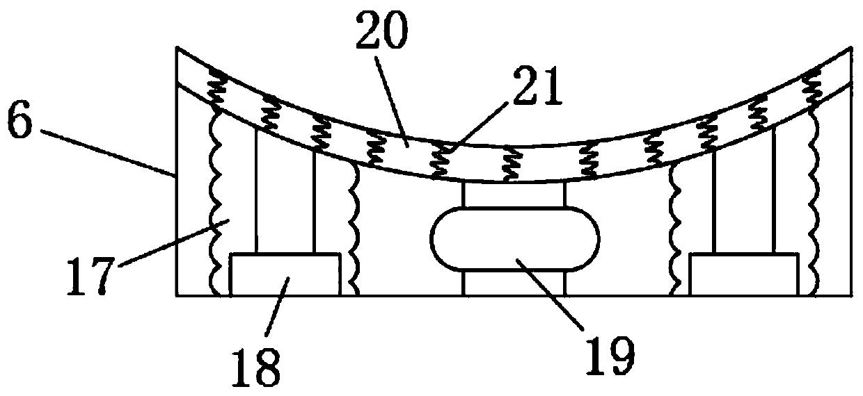
[0031] like Figure 1-3 As shown, the bottom of the ultrasonic cleaning machine 3 is equipped with a shock-absorbing base 6, the ultrasonic cleaning machine 3 is connected with the base 1 through the Shock base two 12 is connected with base 1, and shock absorption base one 6 is made up of hydraulic buffer 18, damping shock absorber 19 and rubber shock absorber 20, and rubber shock absorber 20 bottom is equipped with hydraulic buffer 18 and damping shock absorber 19. The hydraulic buffer 18 is located on both sides of the damping shock absorber 19. The internal structure of the shock-absorbing base 12 is the same as that of the shock-absorbing base 16. The rubber shock-absorbing pad 20 is embedded with a shock-absorbing spring 21, and the hydraulic buffer 18 is external. A shock-absorbing air cushion 17 is installed, and the shock-absorbing air cushion 17 is connected with the rubber shock-absorbing pad 20 .
[0032] In this embodiment, by setting the shock-absorbing base 1 6 ...
PUM
 Abstract
Description
Claims
Application Information
 - R&D
- Intellectual Property
- Life Sciences
- Materials
- Tech Scout
- Unparalleled Data Quality
- Higher Quality Content
- 60% Fewer Hallucinations
Browse by: Latest US Patents, China's latest patents, Technical Efficacy Thesaurus, Application Domain, Technology Topic, Popular Technical Reports.
© 2025 PatSnap. All rights reserved.Legal|Privacy policy|Modern Slavery Act Transparency Statement|Sitemap|About US| Contact US: help@patsnap.com


