GNSS receiver pulse per second-based clock synchronization method

A clock synchronization, second pulse technology, applied in the direction of automatic power control, satellite radio beacon positioning systems, measurement devices, etc. problem to avoid calculation errors

Active Publication Date: 2019-05-17
北京知识产权运营管理有限公司
View PDF22 Cites 9 Cited by
  • Summary
  • Abstract
  • Description
  • Claims
  • Application Information

AI Technical Summary

Problems solved by technology

[0002] The main working sampling clock in integrated circuit design is input by an external clock crystal oscillator and then generated by frequency multiplication or frequency division by a dedicated clock management module such as FPGA internal PLL or MMCM. When the required working clock frequency is lower than 1MHz, then FPGA Internal dedicated clock management resources cannot meet the demand
In some applications with specific requirements for high-precision low-frequency clocks, general clock frequency division circuits cannot provide high-quality and high-reliability clocks without cumulative errors
The error accumulation of clock jitter, drift and clock delay causes the calculation error introduced in the real-time system with high precision and high reliability requirements of long endurance to fail to meet the system index requirements. The present invention provides a clock synchronization method based on the second pulse of GNSS receiver , to solve the problem that the calculation result of the real-time system is not synchronized with the actual one caused by the cumulative error of the low-frequency sampling working clock

Method used


Image

  • GNSS receiver pulse per second-based clock synchronization method
  • GNSS receiver pulse per second-based clock synchronization method

Examples


Embodiment Construction

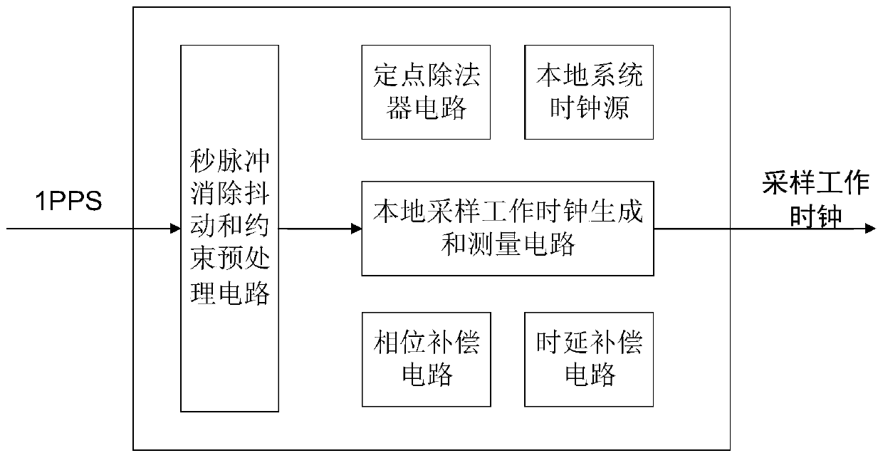
[0019] Attached below figure 1 The present invention is further described.

[0020] The principle of the 1PPS second pulse elimination jitter and constraint preprocessing circuit is to use the clock signal to continuously sample the input 1PPS second pulse signal for n times, and send each sampling result to the shift register. If the n sampling results are all 1, then It is considered that the real signal is 1, otherwise it is 0. Under normal circumstances, the GNSS receiver outputs a 1PPS second pulse signal every 1 second, and the accuracy of the 1PPS signal is ±20ns. In order to prevent the receiver from malfunctioning, the 1PPS signal appears multiple times within 1 second, using a constraint preprocessing circuit The module is used to monitor 1PPS signal. The detection method is: start counting at the falling edge of a certain second pulse, and count the current system clock. If a new second pulse appears before the count value reaches (99%*system clock frequency), it ...


PUM


Abstract

The invention discloses a GNSS receiver pulse per second-based clock synchronization method. According to the method, a GNSS receiver pulse per second 1PPS signal is input to a de-bouncing and constraint preprocessing circuit so as to generate 1PPS anti-shake signals, thereby preventing multiple pulses per second in one second; the 1PPS anti-shake signals are counted by utilizing a first counter so as to obtain a practical frequency value of a system clock signal, and the practical frequency value is input into a fixed-point divider to obtain a cumulative step length of a second counter through formula operation; frequency division is carried out on the system clock signal through the second counter so as to generate a sampling work clock, the bit number of the second counter remains unchanged and the cumulative step length delta of the second counter is changed to change the frequency of a sampling work clock signal; phase compensation is carried out on the sampling work clock, and when each 1PPS anti-shake signal arrives, the sampling work clock is forcibly pulled up to ensure that the sampling work clock is aligned with the 1PPS anti-shake signals; and delay compensation is carried out on the sampling work clock. The method is capable of well solving the problem that accumulative errors of low-frequency sampling work clocks cause calculation results of real-time systems to be asynchronous with practical results.

Description

technical field [0001] The invention relates to the field of clock synchronization of microelectronic integrated circuits, in particular to a clock synchronization method based on the second pulse of a GNSS receiver. Background technique [0002] The main working sampling clock in integrated circuit design is input by external clock crystal oscillator and then generated by multiplication or frequency division by special clock management modules such as FPGA internal PLL or MMCM. When the required working clock frequency is lower than 1MHz, then FPGA Internal dedicated clock management resources cannot meet the demand. In some applications with specific requirements for high-precision low-frequency clocks, general clock frequency division circuits cannot provide high-quality and high-reliability clocks without accumulated errors. The error accumulation of clock jitter, drift and clock delay causes the calculation error introduced in the real-time system with high precision a...

Claims


Application Information

Patent Timeline
Patent Type & Authority Applications(China)
IPC IPC(8): G01S19/25H03L7/18
Inventor 范兆红张开东李迎春
Owner 北京知识产权运营管理有限公司
Why Eureka
Try Eureka