Clock Generation Circuit

a clock generation and circuit technology, applied in the direction of generating/distributing signals, pulse techniques, electric pulse generator details, etc., can solve the problems of complex design of ring oscillators, increased system cost at the same time, and difficult technical implementation, etc., to achieve the effect of simple structur

Inactive Publication Date: 2012-05-31
IPGOAL MICROELECTRONICS (SICHUAN) CO LTD
View PDF1 Cites 3 Cited by
  • Summary
  • Abstract
  • Description
  • Claims
  • Application Information

AI Technical Summary

Benefits of technology

[0006]An object of the present invention is to provide a clock generation circuit whi

Problems solved by technology

But the system cost is increased at the same time.
However, the ring oscillator capable of being compensated by process, voltage, temperature is more complex to be designed, and more difficult to be technical

Method used


Image

  • Clock Generation Circuit
  • Clock Generation Circuit
  • Clock Generation Circuit

Examples


Embodiment Construction

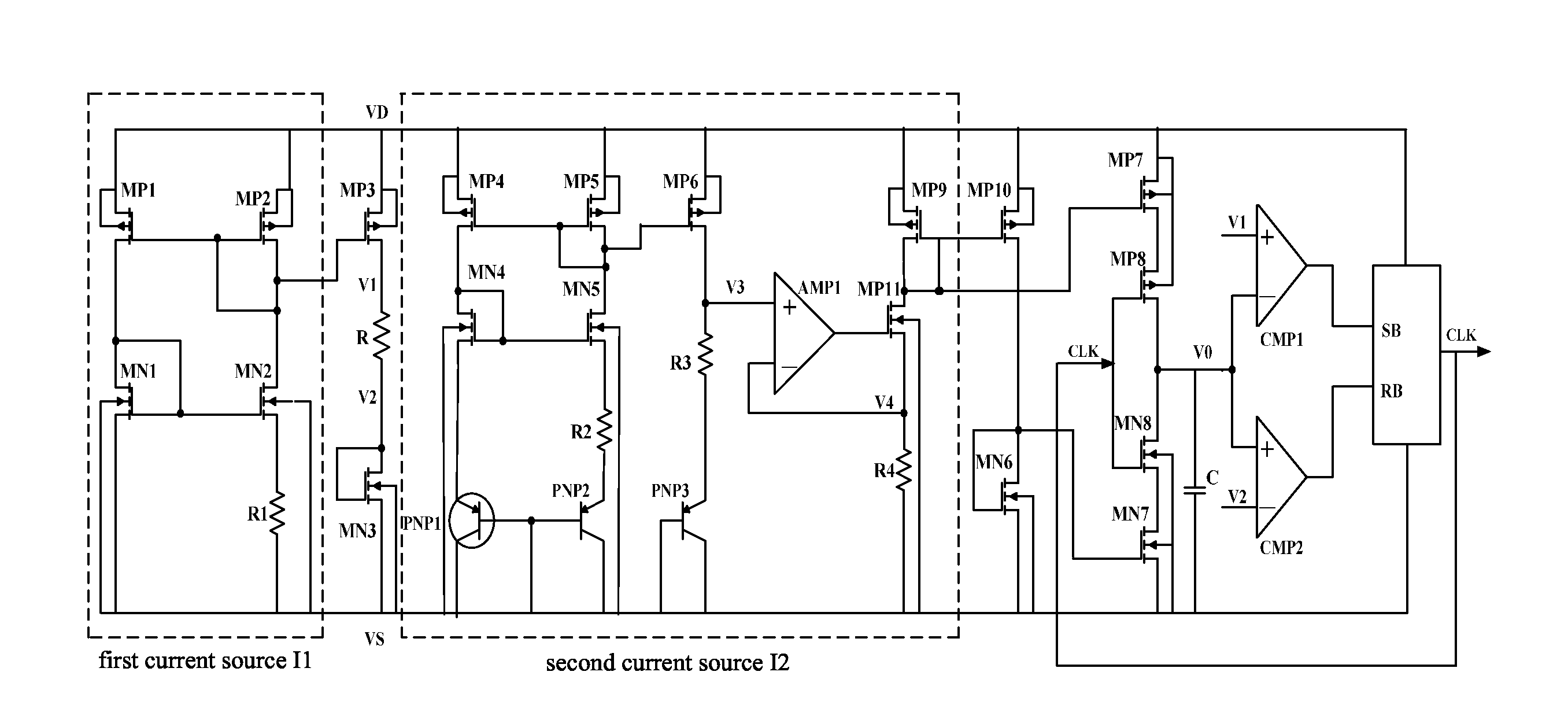
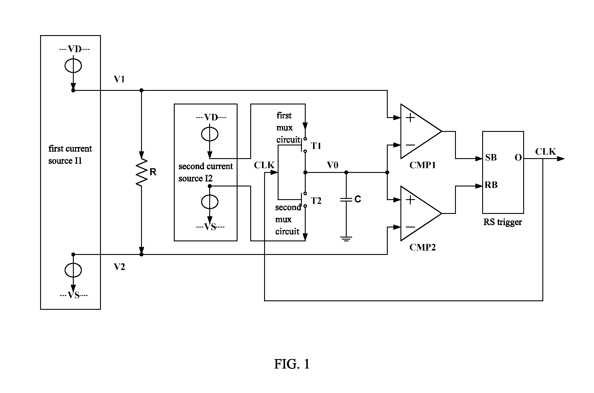
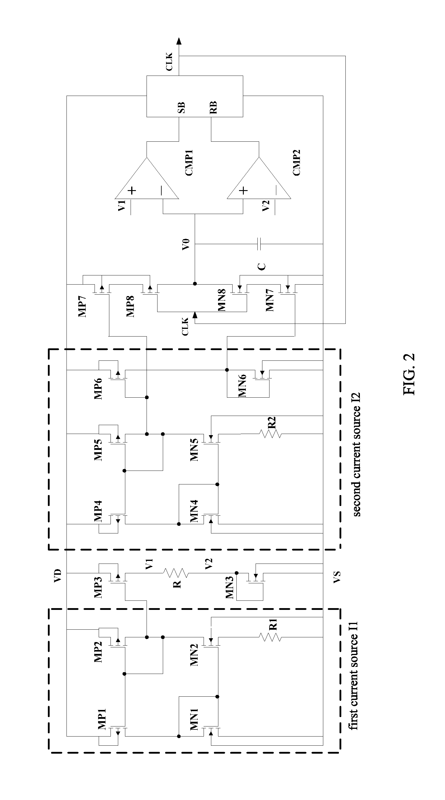
[0013]Referring to FIG. 1 of the drawings, a schematic diagram of a clock generation circuit according to a first preferred embodiment of the present invention is illustrated, in which the clock generation circuit comprises a first current source I1, a second current source I2, a resistor R connected to the first current source I1, a capacitor C, a first comparator CMP1 connected to the capacitor C, a second comparator CMP2 connected to the capacitor C, a RS trigger connected both to the first comparator CMP 1 and the second comparator CMP2, and a first demux circuit and a second demux circuit both connected to the second current source I2.

[0014]According to the first embodiment, the first current source I1 comprises a first power supply terminal and a first ground terminal, wherein the first current source I1 is proportional to

1R2,

and given

I1=K1R2.

The second current source I2 comprises a second power supply terminal and a second ground terminal, wherein the second current source I2...


PUM


Abstract

A clock generation circuit, includes a first current source, a resistor connected to the first current source, a second current source, a first demux circuit connected to the second current source, a second demux circuit connected to the second current source, a capacitor connected to the first demux circuit and the second demux circuit, a first comparator connected to the first current source and the capacitor, a second comparator connected to the first current source and the capacitor, and a RS trigger connected both to the first comparator and the second comparator. The present invention has simple structure, small process variation, and lower cost, and is able to improve the accuracy of the clock with maximum possibility.

Description

BACKGROUND OF THE PRESENT INVENTION[0001]1. Field of Invention[0002]The present invention relates to the field of integrated circuit, and more particularly to a clock generation circuit.[0003]2. Description of Related Arts[0004]A clock generation circuit is an important part of the integrated circuit design. Usually, off-chip crystals or crystal oscillators are used in integrated circuits to provide accurate clock sources. But the system cost is increased at the same time. Therefore, it is very necessary to design a precious on-chip clock generation circuit.[0005]In traditional on-chip clock generation circuits, a ring oscillator capable of being compensated by process, voltage, temperature, etc. or a RC oscillator is often adopted for generating an accurate clock cycle. However, the ring oscillator capable of being compensated by process, voltage, temperature is more complex to be designed, and more difficult to be technically implemented technical. On the other hand, although it i...

Claims


Application Information

Patent Timeline
IPC IPC(8): H03K3/01
CPCH03K4/501
Inventor WU, ZHAOLEILV, YALANWU, GUOSHENG
Owner IPGOAL MICROELECTRONICS (SICHUAN) CO LTD
Why Eureka
Try Eureka