Multistage pressure control complex muffler

A composite muffler and pressure-controlled chamber technology, which is applied to sound-producing equipment, instruments, etc., can solve the problem that ordinary mufflers cannot meet the requirements of high pressure and large flow, and cannot effectively solve the problems of high gas noise pollution and large flow.

Pending Publication Date: 2019-05-17
ZHENJIANG EAST CHINA ELECTRIC POWER EQUIP FACTORY CO LTD
View PDF0 Cites 1 Cited by
  • Summary
  • Abstract
  • Description
  • Claims
  • Application Information

AI Technical Summary

Problems solved by technology

[0002] Noise pollution is one of the four major pollutions in today's society. The muffler is a device that allows airflow to pass through but can prevent or weaken the propagation of sound waves. It is the main technical measure to reduce aerodynamic noise; It will develop from the 2nd generation, 2nd generation and a half technology to the 3rd generation technology, which will also bring new development opportunities for nuclear power enterprises; the "Nuclear Power Medium and Long-term Development Plan" requires to accelerate the construction of independent nuclear power equipment manufacturing, strengthen research and development, and focus on Make breakthroughs in the design and manufacturing technology of key equipment; the "Notice of the General Office of the National Development and Reform Commission on Organizing and Carrying out Special Projects for the Development of National Major Technical Equipment" lists "complete sets of equipment for million-kilowatt nuclear power plants" as a special content for the development of national major technical equipment; for example The steam parameters of the VDA system of Hualong No. 1 nuclear power unit are very high, which are higher than those of other nuclear power units such as CPR1000, resulting in high pressure and large flow entering the muffler. Ordinary mufflers cannot meet the requirements of high pressure and large flow, and cannot be effective. Solve the high noise pollution of gas emissions

Method used


Image

  • Multistage pressure control complex muffler

Examples


Embodiment Construction

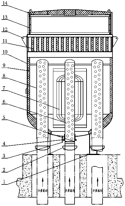
[0018] As shown in the figure, a multi-stage pressure control composite muffler includes a casing 10 that is sealed and connected through the legs 1 and fixedly installed outside the atmospheric exhaust port. The middle part of the inner cavity of the casing 10 is provided with a The main shunt pipe 6, the top of the main shunt pipe 6 is closed, and the lower end is fixedly connected to the atmospheric exhaust port. The lower end of the inner cavity of the main shunt pipe 6 is provided with a throttling orifice 5, which constitutes a primary pressure control structure; the wall of the main shunt pipe 6 There are a number of circular through holes from top to bottom, forming a secondary pressure control structure; the middle section of the main shunt pipe 6 is coaxially arranged and fixedly connected with a multi-layer pressure control cylinder 7, and the height and diameter of the multi-layer pressure control cylinder 7 are according to The sequence increases from the inside to...


PUM


Abstract

The invention discloses a multistage pressure control complex muffler. A restriction orifice plate is arranged at the lower end of an inner cavity of a main manifold in a casing; a plurality of roundholes are spread on the wall part of the main manifold from top to bottom to form a second-stage pressure control structure; multiple layers of pressure control cylinders are coaxially arranged and are fixedly connected with the outer part of the main manifold; a plurality of round through holes are distributed on the wall of the pressure control cylinder of each layer from top to bottom; the round through holes in the walls of two adjacent layers of pressure control cylinders are staggered distributed in a spaced manner; a second manifold is arranged in the casing to form a fourth-stage pressure control structure; large pressure drop exhausted by an atmosphere exhaust opening is dispersed to bear, so that air current discharged from the atmosphere exhaust opening is changed from pressurejump evacuation into pressure gradient evacuation, and further strong jet noise produced by large pressure drop exhaust is avoided; gas is jetted from small holes and is assisted with a resistance sound absorber for further absorbing sound, the internal pressure drop process of equipment can be controlled, atmospheric emission noise is reduced, the noise spectrum quality is improved, and a noise pollution control goal is achieved; the multistage pressure control complex muffler meets the use requirements of an atmospheric exhaust regulating valve for nuclear power on high pressure and mass flow and has good muffling effect.

Description

technical field [0001] The invention relates to a multi-stage pressure-control composite muffler for controlling the noise discharge of the main steam relief valve of the third-generation nuclear power system and the main steam relief valve of other reactor-type nuclear power units, or the discharge pipe of the similar valve. Background technique [0002] Noise pollution is one of the four major pollutions in today's society. The muffler is a device that allows airflow to pass through but can prevent or weaken the propagation of sound waves. It is the main technical measure to reduce aerodynamic noise; It will develop from the 2nd generation, 2nd generation and a half technology to the 3rd generation technology, which will also bring new development opportunities for nuclear power enterprises; the "Nuclear Power Medium and Long-term Development Plan" requires to accelerate the construction of independent nuclear power equipment manufacturing, strengthen research and developme...

Claims


Application Information

Patent Timeline
IPC IPC(8): G10K11/16
Inventor 张武军许多陈广贤龚家敏
Owner ZHENJIANG EAST CHINA ELECTRIC POWER EQUIP FACTORY CO LTD
Why Eureka
Try Eureka