Float valve tower cleaning system and cleaning method

A cleaning system and valve tower technology, applied in the valve tower cleaning system and the cleaning field, can solve the problems of decreased processing capacity, shortened inspection and maintenance time, and floating valve jammed trays, etc., and achieves high operational flexibility and shortens inspection and maintenance. Time, avoid the effect of dismantling and cleaning

Pending Publication Date: 2022-07-22
河南开祥精细化工有限公司
View PDF0 Cites 0 Cited by
  • Summary
  • Abstract
  • Description
  • Claims
  • Application Information

AI Technical Summary

Problems solved by technology

[0005] The beneficial effects of adopting the technical solution of the present invention are: by cleaning the floating valve tower, the impurities in the tower are removed, the heat transfer effect of the tray is improved, and the system operation is prevented from being affected by the liquid flooding caused by the large pressure difference of the floating valve tower. Dismantling and cleaning of the tower tray shortens the inspection and maintenance time; ensures the high efficiency of the float valve tower, large operating flexibility, good processing capacity, and good mass transfer effect, and solves the problem of internal impurities accumulated after the float valve tower has been operated for a long time, causing the float valve to be stuck Astringent, dirty trays, affect heat transfer effect, and reduce processing capacity

Method used


Image

  • Float valve tower cleaning system and cleaning method
  • Float valve tower cleaning system and cleaning method

Examples


Embodiment 1

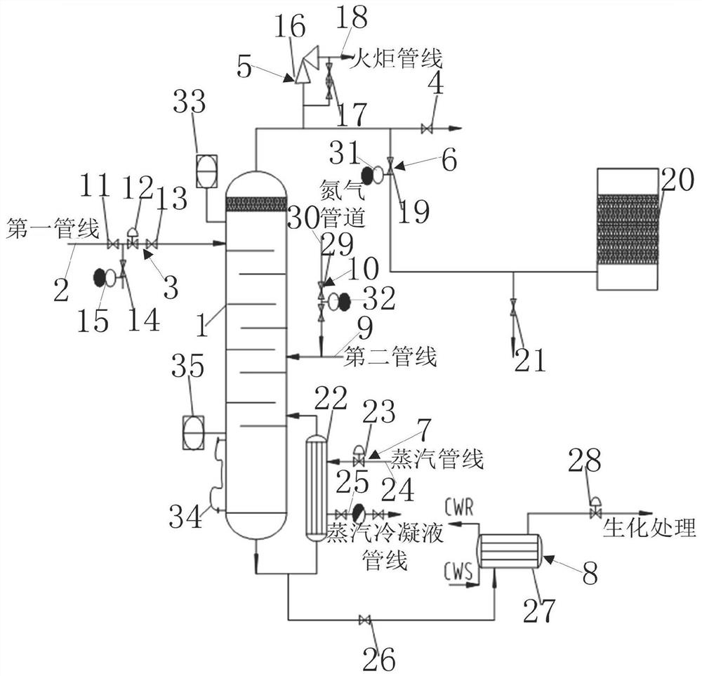
[0075] like figure 1 As shown, a floating valve tower cleaning system includes: a central control unit, an evaporation unit and a cooling unit that are connected in sequence; the controlled end of the central control unit is connected to the control end of the evaporation unit of the central control unit; the evaporation unit includes a float The valve tower, the return line is connected to the top of the float valve tower, the control valve group is installed on the return line, the DN50 demineralized water pipeline and the demineralized water valve are installed between the reflux control valve and the front valve of the return control valve, and the “8” blind is installed. plate (blind position during normal operation, and open position before cleaning the float valve tower). A gas phase outlet valve is installed at the outlet of the gas phase pipeline of the float valve tower. The gas phase pipeline is provided with a safety valve and a safety valve bypass. The other end o...

Embodiment 2

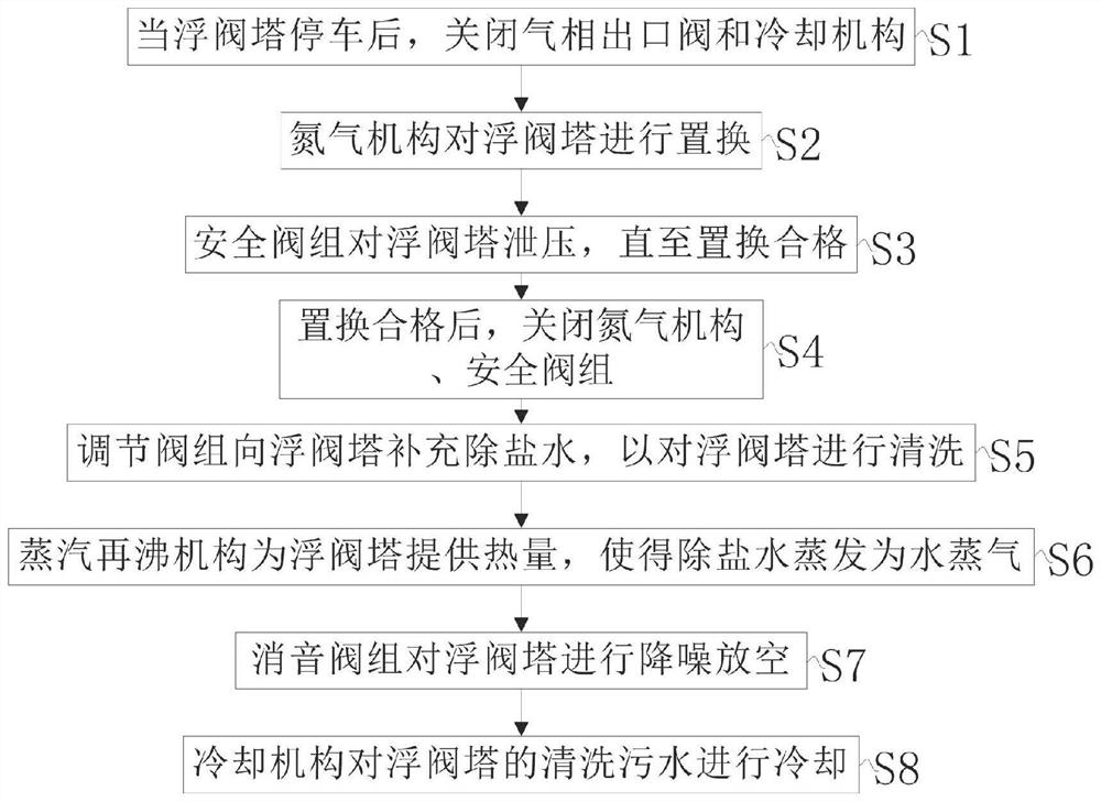
[0077] A kind of valve tower cleaning system of Embodiment 1, further, when the valve tower is stopped, close the gas phase outlet valve of the valve tower gas phase pipeline and the liquid phase outlet valve of the float valve tower, and open the nitrogen two-way valve to the float valve tower ( Replacement), the pressure is relieved through the bypass of the safety valve, and the nitrogen content ≥ 99.5% is regarded as qualified for the replacement.

[0078] When cleaning the float valve tower, close the front valve of the backflow control valve, open the back valve of the backflow control valve, and the demineralized water valve to control the flow of the cleaning water source through the backflow control valve. When cleaning the float valve tower, the remote transmission pressure of the float valve tower is controlled by adjusting the inlet valve of the muffler. A guide shower is installed from the gas phase of the float valve tower to the low point of the muffler pipeline...


PUM


Abstract

The invention provides a floating valve tower cleaning system and method, and the floating valve tower cleaning system comprises a floating valve tower, a first pipeline, a regulating valve group, a gas phase outlet valve, a safety valve group, a silencing valve group, a steam reboiling mechanism, a cooling mechanism, a second pipeline and a nitrogen mechanism, the first pipeline is connected with the top of the floating valve tower through a pipeline by virtue of the adjusting valve group, the gas phase outlet valve is connected with the top of the floating valve tower through a pipeline, and the safety valve group is connected with the pipeline between the gas phase outlet valve and the floating valve tower through a pipeline; the noise reduction valve group is connected with a pipeline between the gas phase outlet valve and the safety valve group through a pipeline, the steam reboiling mechanism and the cooling mechanism are respectively connected with the bottom of the float valve tower through pipelines, the second pipeline is connected with the middle of the float valve tower, and the nitrogen mechanism is connected to the second pipeline.

Description

technical field [0001] The invention relates to the technical field of valve tower cleaning equipment, in particular to a valve tower cleaning system and a cleaning method. Background technique [0002] Float valve trays are widely used in petrochemical industry. Float valve trays are commonly used trays, which open many square or circular holes on the tray, each hole has a valve plate, and the gas passes through the valve hole. The valve plate is lifted up and injected in the horizontal direction. When passing through the liquid layer, the gas and liquid two phases form a foam state to conduct heat and mass transfer processes. Since the opening of the valve plate can be changed with the gas speed, the valve plate can be automatically closed under the action of gravity at low gas speed, reducing leakage. Therefore, it has high efficiency, large operation flexibility, good processing capacity, small mist entrainment, long contact time, good mass transfer effect; and simple s...

Claims


Application Information

Patent Timeline
Patent Type & Authority Applications(China)
IPC IPC(8): B08B9/08B01D3/00B01D3/42B01B1/00
CPCB08B9/08B01D3/00B01D3/42B01B1/00
Inventor 李冰李建立鲁军和进伟徐亮亮王志军靳明张方贾丹赵明霞陈文礼赵宾张勇刘贵宾孙燕王佳佳尚凤玲张欣
Owner 河南开祥精细化工有限公司
Why Eureka
Try Eureka