A flexible display panel, manufacturing method thereof, and display device

A flexible display and manufacturing method technology, applied in identification devices, semiconductor/solid-state device manufacturing, instruments, etc., can solve problems such as difficult etching and removal of functional layers and the influence of flexible substrates

Active Publication Date: 2020-11-27
BOE TECH GRP CO LTD
View PDF3 Cites 0 Cited by
  • Summary
  • Abstract
  • Description
  • Claims
  • Application Information

AI Technical Summary

Problems solved by technology

[0005] The present invention provides a flexible display panel, a manufacturing method thereof, and a display device to solve the problem of opening a hole on the screen. The functional layer in the area to be opened is difficult to completely etch and remove, and the remaining material will affect the subsequent etching. Issues affecting flexible substrates

Method used


Image

  • A flexible display panel, manufacturing method thereof, and display device
  • A flexible display panel, manufacturing method thereof, and display device
  • A flexible display panel, manufacturing method thereof, and display device

Examples


Embodiment 1

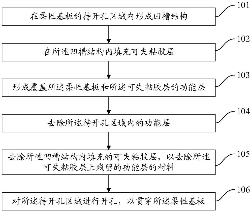
[0038] refer to figure 1 , which shows a flow chart of a method for manufacturing a flexible display panel according to an embodiment of the present invention, which may specifically include the following steps:

[0039] Step 101 , forming a groove structure in a region to be opened on the flexible substrate.

[0040] In the embodiment of the present invention, a groove structure is formed in the area to be opened reserved on the flexible substrate, and the groove structure may include only one groove, or may include multiple grooves.

[0041] When the groove structure only includes one groove, the plasma etching process is used to form a groove in the area to be opened on the flexible substrate, the depth of the groove is smaller than the thickness of the flexible substrate, for example, the groove can be The depth is set to 1 / 3-1 / 2 of the thickness of the flexible substrate, and the aperture of the groove is equal to the aperture of the area to be drilled.

[0042] When th...

Embodiment 2

[0066] An embodiment of the present invention provides a flexible display panel, which is manufactured by using the above method for manufacturing a flexible display panel.

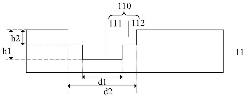
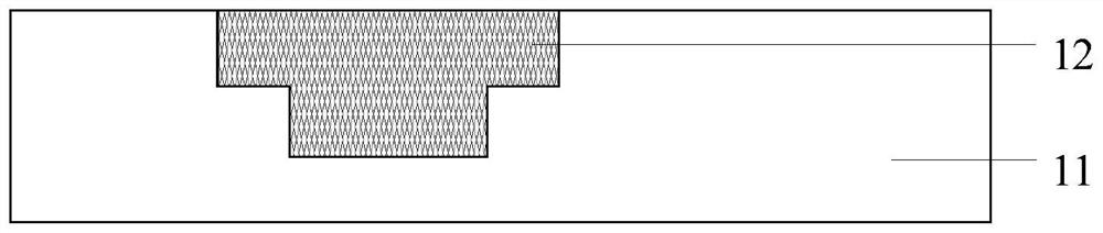
[0067] Firstly, a groove structure 110 is formed in the area to be opened on the flexible substrate 11, and the removable adhesive layer 12 is filled in the groove structure 110. Then, the functional layer 13 is formed on the flexible substrate 11, so that the functional layer 13 covers the flexible substrate. The substrate 11 and the removable adhesive layer 12 are removed by etching the functional layer 13 in the area to be opened, and then the removable adhesive layer 12 filled in the groove structure 110 is removed, and the removed groove structure 110 is filled with When the removable adhesive layer 12 is used, the remaining functional layer material on the removable adhesive layer 12 can be removed at the same time, and finally, the area to be opened is etched to complete the opening to penetrate the...


PUM

PropertyMeasurementUnit
thicknessaaaaaaaaaa
pore sizeaaaaaaaaaa
peel strengthaaaaaaaaaa

Abstract

The invention provides a flexible display panel, a preparation method of the flexible display panel, and a display device, and relates to the technical field of display. The preparation method comprises the steps of forming a groove structure in a to-be-opened region of a flexible substrate, filling a visual adhesive layer in the groove structure, forming a functional layer covering the flexible substrate and the visual adhesive layer, removing the functional layer in the to-be-opened region, removing the visual adhesive layer to remove a material of the functional layer remaining on the visual adhesive layer, and opening the to-be-opened region. According to the method, the groove structure is formed in the to-be-opened region of the flexible substrate, the visual adhesive layer is filledin the groove structure, the material of the functional layer remains on the visual adhesive layer when the functional layer in the to-be-opened region is removed, and the material of the functionallayer remaining on the visual adhesive layer can be removed when the visual adhesive layer filled in the groove structure is removed, so that no material remains on the flexible substrate; and etchingof the flexible substrate can be more uniform and thorough when the flexible substrate is subsequently opened.

Description

technical field [0001] The invention relates to the field of display technology, in particular to a flexible display panel, a manufacturing method thereof, and a display device. Background technique [0002] With the rapid development of display technology, OLED (Organic Light Emitting Diode, organic electroluminescent device) has a wide range of application prospects due to its advantages of high response, high contrast and flexibility, especially in flexible displays. , which can better reflect the advantages of OLED itself. [0003] At present, in order to increase the screen-to-body ratio of the display device, a full screen without borders is usually used. The full screen includes a special-shaped screen. The flexible substrate in the hole area is etched to form openings for placing cameras, earpieces, sensors and other components. [0004] However, since the thin film encapsulation layer, metal electrodes and other inorganic layers in the functional layer in the area...

Claims


Application Information

Patent Timeline
Patent Type & Authority Patents(China)
IPC IPC(8): H01L27/32H01L51/56G09F9/30
Inventor 罗程远王涛
Owner BOE TECH GRP CO LTD
Why Eureka
Try Eureka