
Space-fed high-gain end-fire array antenna based on electromagnetic surface technology

An electromagnetic surface, end-fire array technology, applied in space feed arrays, linear waveguide feed arrays, and individually energized antenna arrays, etc. Coupling limiting, increasing gain, low profile effects

Active Publication Date: 2021-01-22
TSINGHUA UNIV
View PDF4 Cites 0 Cited by
  • Summary
  • Abstract
  • Description
  • Claims
  • Application Information

AI Technical Summary

Problems solved by technology

Due to the serious unit mutual coupling in the traditional end-fire array, the array size is limited, and the antenna gain is difficult to increase

Method used


Image

  • Space-fed high-gain end-fire array antenna based on electromagnetic surface technology
  • Space-fed high-gain end-fire array antenna based on electromagnetic surface technology
  • Space-fed high-gain end-fire array antenna based on electromagnetic surface technology

Examples


Embodiment Construction

[0022] Embodiments of the present invention are described in detail below, examples of which are shown in the drawings, wherein the same or similar reference numerals designate the same or similar elements or elements having the same or similar functions throughout. The embodiments described below by referring to the figures are exemplary and are intended to explain the present invention and should not be construed as limiting the present invention.

[0023] The space-fed high-gain end-fire array antenna based on the electromagnetic surface technology proposed according to the embodiments of the present invention will be described below with reference to the accompanying drawings.

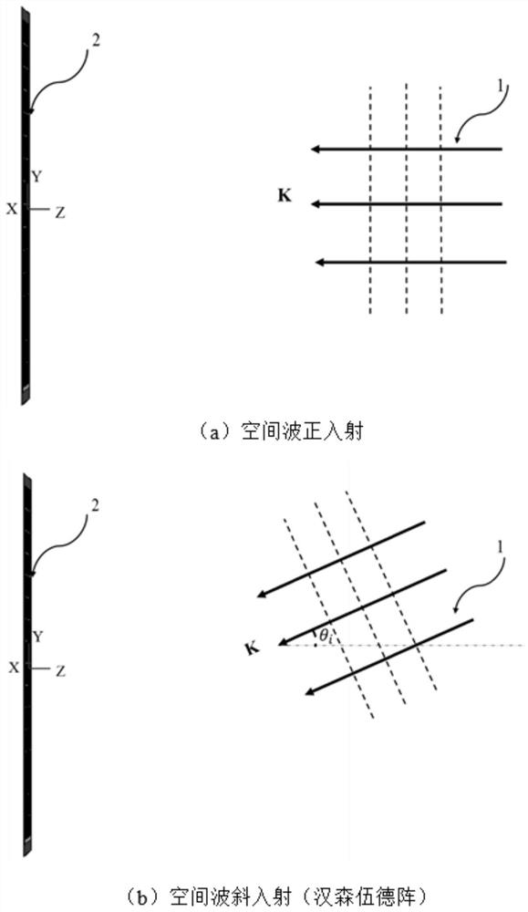
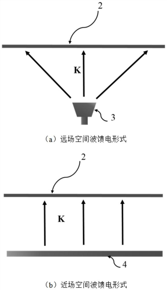
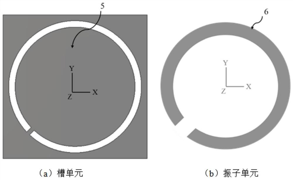
[0024] figure 1 It is a structural schematic diagram of a space-fed high-gain end-fire array antenna based on electromagnetic surface technology according to an embodiment of the present invention.

[0025] Such as figure 1 As shown, the space-fed high-gain end-fire array antenna based on electro...


PUM


Abstract

The invention discloses a space-fed high-gain end-fire array antenna based on electromagnetic surface technology, comprising: a primary feed source for transmitting and / or receiving electromagnetic waves; and a single-layer and / or multi-layer extremely thin The combined surface of dielectric and metal is used to convert the electromagnetic wave emitted by the primary feed into an end-fire focused beam, or to converge the space wave received in the end-fire direction into the primary feed. The antenna of the embodiment of the present invention has the following significant advantages: (1) It only needs an extremely thin electromagnetic surface, and has the advantages of light weight, extremely low profile, and low manufacturing cost. (2) The reflection beam and the transmission beam are integrated, which increases the utilization rate of the antenna, saves the space occupied by the antenna, and further reduces the weight of the antenna. (3) The antenna gain will increase with the increase of the aperture size.

Description

technical field [0001] The invention relates to the technical field of antennas, in particular to a space-fed high-gain end-fire array antenna based on electromagnetic surface technology. Background technique [0002] The airborne radar system undertakes the task of air patrol and alert, makes up for the blind spots of ground radar, monitors, detects, tracks and identifies incoming air targets, and monitors the battlefield situation. In order to better accomplish its intended tasks, an ideal airborne radar should meet two conditions: one is that the beam covers a wide airspace and the radar blind area is small; capacity and mobility. In practical applications, these two conditions are difficult to be satisfied at the same time, because the principle of the side-fire phased array determines that to make the high-gain beam cover a certain airspace, the corresponding airborne phased array antenna must Have a correspondingly large enough caliber. To ensure that the scanning b...

Claims


Application Information

Patent Timeline
Patent Type & Authority Patents(China)
IPC IPC(8): H01Q1/50H01Q1/52H01Q3/30H01Q13/02H01Q13/20H01Q21/00H01Q21/06H01Q1/28
CPCH01Q21/0018H01Q21/062H01Q21/064H01Q9/065H01Q9/16H01Q21/005
Inventor 杨帆王敏许慎恒李懋坤
Owner TSINGHUA UNIV
Learn More