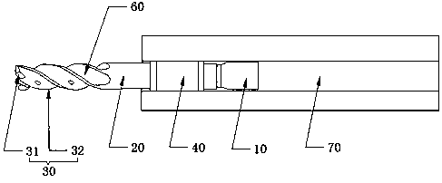
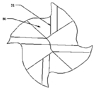
Precise reaming reamer

A reamer, precise technology, applied in the direction of reamer, metal processing equipment, manufacturing tools, etc., can solve the problems of increasing scrap rate, easy deformation of products, and easy deformation, so as to improve the qualified rate of finished products, reduce the residence time, and ensure The effect of machining accuracy

Inactive Publication Date: 2019-05-21
江苏扬碟钻石工具有限公司
View PDF3 Cites 0 Cited by
  • Summary
  • Abstract
  • Description
  • Claims
  • Application Information

AI Technical Summary

Problems solved by technology

[0002] Milling cutters are generally specially designed and manufactured for machining workpieces with specific shapes. They are usually used to process angled surfaces, groove surfaces, special-shaped holes and stepped surfaces, etc. The cutting edge shape of milling cutters generally matches the shape of the workpiece. In order to form the desired specific shape on the workpiece through one-time processing, but after using traditional milling cutters, the product is easily deformed
[0003] At the same time, for deep holes, in order to meet deep hole processing, the shank adopts a long rod structure. Because the tool shank is too long, the ability to transmit torque is reduced, and it is easy to deform under the action of torque, which cannot guarantee the size and shape accuracy of deep hole processing. , causing unqualified products and increasing the scrap rate

Method used


Image

  • Precise reaming reamer
  • Precise reaming reamer

Examples


Embodiment Construction

[0018] The present invention will be described in further detail below in conjunction with the accompanying drawings.

[0019] It should be noted that all directional indications (such as up, down, left, right, front, back...) in the embodiments of the present invention are only used to explain the relative relationship between the various components in a certain posture (as shown in the drawings). When the positional relationship, movement conditions, etc., if the specific posture changes, the directional indication will also change accordingly. In addition, the descriptions involving "first", "second" and so on in the present invention are only for descriptive purposes, and should not be understood as indicating or implying their relative importance or implicitly indicating the quantity of the indicated technical features. Thus, the features defined as "first" and "second" may explicitly or implicitly include at least one of these features. In addition, the technical soluti...


PUM


Abstract

The invention discloses a precise reaming reamer, and relates to the technical field of reamers. The reamer comprises a reamer head, a reamer handle and an edge part; a cylindrical guiding section which is coaxial with the reamer handle is formed in the reamer handle; the diameter of the cylindrical guiding section is larger than that of the reamer handle, and is smaller than a nominal diameter ofthe reamer head; the edge part is integrally moulded on one end, which is far away from the reamer head, of the reamer handle; besides, the edge part comprises bottom edges located at the tail end ofthe edge part and side edges which are wound on the side surface of the edge part; the angles of the bottom edges distributing or extending toward a geometrical center are minus; slag accommodation grooves are formed between the bottom edges and bottom edge backs which extend toward the side edges; the bottom edges extend toward the side edges and are integrally connected to the side edges; a slag discharging groove with a waved shape is formed by every two adjacent side edges; and each slag discharging groove is connected to the tail end f the corresponding slag accommodation groove.

Description

technical field [0001] The invention relates to the technical field of milling cutters, in particular to a reamer with precise reaming. Background technique [0002] Milling cutters are generally specially designed and manufactured for machining workpieces with specific shapes. They are usually used for machining angled surfaces, groove surfaces, special-shaped holes and stepped surfaces, etc. The cutting edge shape of milling cutters generally matches the shape of the workpiece. In order to form the required specific shape on the workpiece through one-time processing, but after using traditional milling cutters, the product is easily deformed. [0003] At the same time, for deep holes, in order to meet deep hole processing, the shank adopts a long rod structure. Because the tool shank is too long, the ability to transmit torque is reduced, and it is easy to deform under the action of torque, which cannot guarantee the size and shape accuracy of deep hole processing. , resu...

Claims


Application Information

Patent Timeline
Patent Type & Authority Applications(China)
IPC IPC(8): B23D77/00
Inventor 唐健郑敏利姜彬陈涛李哲张为王波
Owner 江苏扬碟钻石工具有限公司
Why Eureka
Try Eureka