
Electromagnetic field prediction method of three-dimensional FEM mixed with two-dimensional FMM

A prediction method and electromagnetic field technology, applied in the field of electromagnetic field and microwave, can solve the problems of large demand for computing resources, high cost, high cost of manpower, material resources, financial resources, etc., to achieve rapid two-dimensional generation, solve complexity, and high calculation accuracy Effect

Active Publication Date: 2019-05-21
XIDIAN UNIV
View PDF4 Cites 4 Cited by
  • Summary
  • Abstract
  • Description
  • Claims
  • Application Information

AI Technical Summary

Problems solved by technology

[0003] The existing main method of monitoring electromagnetic fields is experimental measurement. This method is to predict the distribution of electromagnetic fields in residential rooms by means of measurements under the condition of base station antenna radiation. First of all, this method cannot exclude the influence of measurement personnel and test probes Secondly, this method needs to spend a lot of manpower, material resources and financial resources, which cannot meet the growing demand
Another commonly used method for monitoring electromagnetic fields is numerical calculation. For example, the full-wave method-the method of moments (MoM) combined with high-performance computing technology is used for numerical calculation simulation. Although this method has high calculation accuracy, it requires a lot of computing resources. , The cost is high, and there are certain limitations in the scale of the problem that can be handled at the same time, it is difficult to meet the actual needs

Method used


Image

  • Electromagnetic field prediction method of three-dimensional FEM mixed with two-dimensional FMM
  • Electromagnetic field prediction method of three-dimensional FEM mixed with two-dimensional FMM
  • Electromagnetic field prediction method of three-dimensional FEM mixed with two-dimensional FMM

Examples


specific Embodiment 1

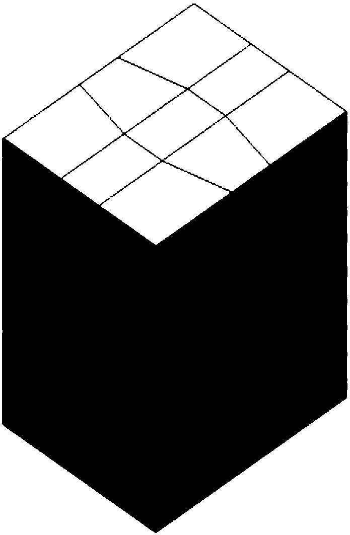
[0052] Using a workstation, 2 Intel (Intel) Xeon six-core E5-2620 processors, 192GB DDR3 memory, and a total capacity of 5T hard disk for specific implementation, such as figure 2 As shown, the residential building with a height of five floors is used as the selected electromagnetic field distribution area of ​​embodiment 1. The three-dimensional size of the building is 10m × 8m × 15m, the wall thickness is 30cm, the relative permittivity of the wall is 3.916, and the yoz surface The size of the window is 2m×1.5m, and the size of the xoz door is 2m×2.2m. A half-wave symmetrical dipole antenna placed vertically with a frequency of 100MHz is used as the radiation source. The center of the half-wave symmetrical dipole antenna is located at (5m, 20m, 7.5m):

[0053] Firstly, select the position of the observation site, set it as the plane with a height of h=7.5m and the straight line from (-4, 12, 7.5) to (15, 12, 7.5), according to the height of the observation site h=7.5m , th...

specific Embodiment 2

[0054] Using a workstation, 2 Intel (Intel) Xeon six-core E5-2620 processors, 192GB DDR3 memory, and a total capacity of 5T hard disk for specific implementation, such as figure 2 As shown, the residential building with a height of five floors is used as the selected electromagnetic field distribution area of ​​embodiment 1. The three-dimensional size of the building is 10m × 8m × 15m, the wall thickness is 30cm, the relative permittivity of the wall is 3.916, and the yoz surface The size of the window is 2m×1.5m, and the size of the xoz door is 2m×2.2m. A half-wave symmetric dipole antenna with a frequency of 150MHz is used as the radiation source. The center of the half-wave symmetric dipole antenna is located at (5m, 20m, 7.5m):

[0055] Firstly, select the position of the observation site, set it as the plane with a height of h=7.5m and the straight line from (-4, 12, 7.5) to (15, 12, 7.5), according to the height of the observation site h=7.5m , the two-dimensional Gaus...

specific Embodiment 3

[0056] Using a workstation, 2 Intel (Intel) Xeon six-core E5-2620 processors, 192GB DDR3 memory, and a total capacity of 5T hard disk for specific implementation, such as figure 2 As shown, the residential building with a height of five floors is used as the selected electromagnetic field distribution area of ​​embodiment 1. The three-dimensional size of the building is 10m × 8m × 15m, the wall thickness is 30cm, the relative permittivity of the wall is 3.916, and the yoz surface The size of the window is 2m×1.5m, and the size of the xoz door is 2m×2.2m. A half-wave symmetric dipole antenna with a frequency of 900MHz is used as the radiation source. The center of the half-wave symmetric dipole antenna is located at (5m, 20m, 7.5m):

[0057] Firstly, select the position of the observation site, set it as the plane with a height of h=7.5m and the straight line from (-4, 12, 7.5) to (15, 12, 7.5), according to the height of the observation site h=7.5m , the two-dimensional Gaus...


PUM

PropertyMeasurementUnit
Wall thicknessaaaaaaaaaa

Abstract

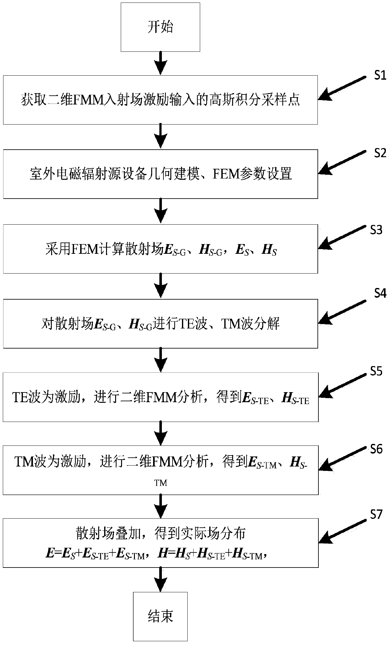
The invention discloses an electromagnetic field prediction method of a three-dimensional FEM mixed with a two-dimensional FMM. The electromagnetic field calculation method of the three-dimensional FEM mixed with the two-dimensional FMM is innovatively provided for the first time; the method comprises the steps of FEM calculation, two-dimensional FMM analysis, scattered field superposition and thelike. the indoor electromagnetic field distribution of the urban housing under the radiation condition of each related electromagnetic radiation source is simulated; according to the method, the capacity of the FEM for processing complex materials and structural targets and the capacity of the two-dimensional FMM for processing super-electric large targets or environments are fully combined, andan efficient and feasible means is provided for achieving civil hot spot problems such as indoor and outdoor electromagnetic field distribution prediction of high-rise buildings. Compared with a traditional high-frequency method for electromagnetic field prediction, the technology is higher in calculation precision and efficiency, and the scale of solvable problems is larger; and two-dimensional modeling is adopted for the high-rise buildings, so that the complexity that three-dimensional modeling needs to be adopted in a traditional method is solved, and rapid two-dimensional generation of urban high-rise building groups can be automatically realized.

Description

technical field [0001] The invention belongs to the technical field of electromagnetic fields and microwaves, and in particular relates to an electromagnetic field prediction method of a three-dimensional FEM mixed with a two-dimensional FMM. technical background [0002] With the rapid development of mobile communication, mobile base stations can be seen everywhere in cities and towns. These base stations and other electromagnetic radiation sources, such as broadcast signals from radio stations and electromagnetic radiation from high-voltage wires, together constitute a complex electromagnetic field environment in the city. As people pay more and more attention to their health, they also pay more attention to the possible damage caused by electromagnetic radiation. Residents often reject the installation of base station antennas near their homes, and relevant departments often receive a large number of complaints. How to ensure the blind areas without communication signals ...

Claims


Application Information

Patent Timeline
IPC IPC(8): G06F17/50
Inventor 赵勋旺左胜张玉林中朝袁峰
Owner XIDIAN UNIV
Learn More