Energy event driving method and system

An event-driven, driving system technology, applied in electric vehicles, electrical components, vehicle components, etc., can solve the problems of long ineffective working time, corresponding change of drive, low driving efficiency, etc., to reduce ineffective working time, energy and hardware. attrition, effect without supervision

Inactive Publication Date: 2019-05-21
UNIV OF ELECTRONICS SCI & TECH OF CHINA
View PDF2 Cites 1 Cited by
  • Summary
  • Abstract
  • Description
  • Claims
  • Application Information

AI Technical Summary

Problems solved by technology

[0004] The purpose of the present invention is: the present invention provides an energy event driving method and system to solve the problem that the existing energy driving cannot change the driving according to the specific conditions of the load and the environment, resulting in low driving efficiency, large energy consumption, and invalid working time long question

Method used


Image

  • Energy event driving method and system
  • Energy event driving method and system

Examples


Embodiment 1

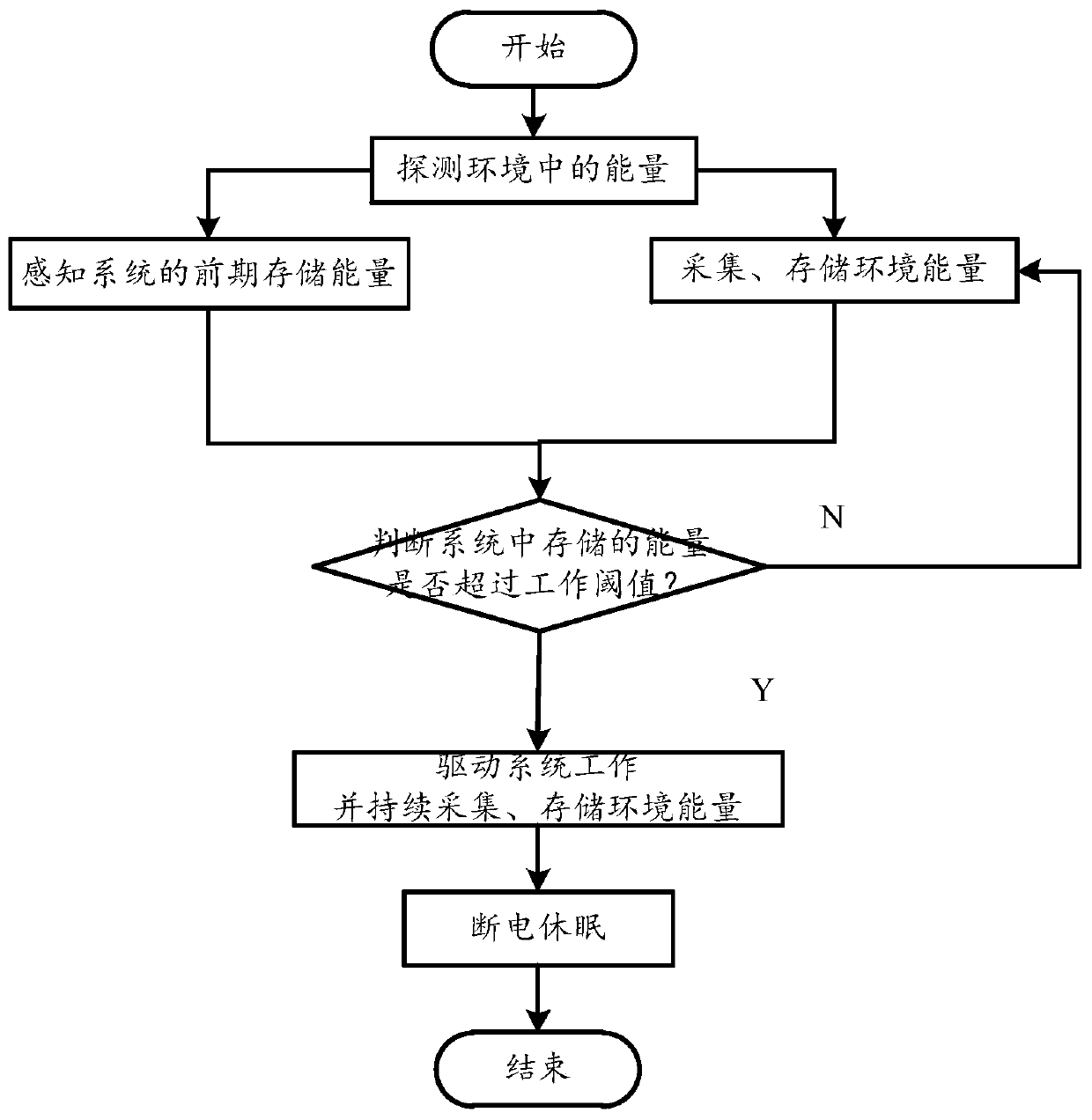
[0061] Such as Figure 1-2 As shown, an energy event-driven method includes the following steps:

[0062] Step 1: Detect energy in the environment;

[0063] Step 2: Collect and store the energy in the detected environment, and at the same time perceive the stored energy in the early stage of the system;

[0064] Step 3: According to step 2, judge whether the stored energy of the system exceeds the system working threshold. If it exceeds, drive the system to work and continue to collect and store the energy in the detected environment, then skip to step 4; if not, return to step 2 Continue to collect and store energy in the environment;

[0065] Step 4: Drive the system into a power-off sleep state according to demand or energy exhaustion.

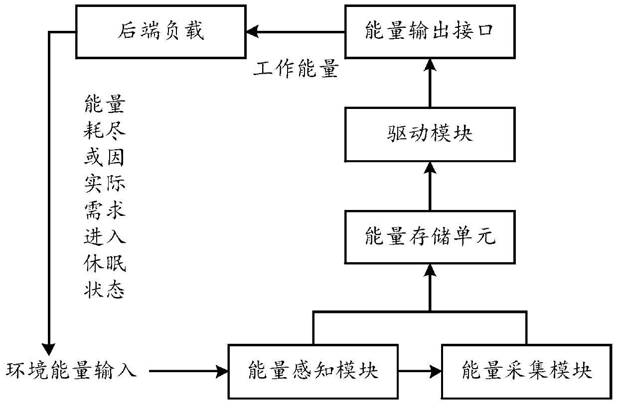
[0066] An energy event driven system comprising

[0067] The energy collection module is used to collect the detected environmental energy, convert the collected energy into system working energy and send it to the energy storage unit; ...

Embodiment 2

[0076] Based on Embodiment 1, the difference of this embodiment is that: the energy sensing module of the system senses the working energy in the energy storage unit while the energy collection module collects energy; the driving module is used to judge whether the working energy in the energy storage unit exceeds the system Working threshold, and control the energy output interface of the system, connect the working energy to the back-end load or drive the system into a power-off sleep state.

[0077] The energy storage unit of the system provides energy to the load to make the load work. The energy in the environment changes all the time. The power collected by the energy harvester cannot match the demand of the back-end load in real time, so the collected energy must be stored in the energy storage unit to provide Use it for the backend load. The energy storage unit stores energy through collection and conversion, and supplies energy to the load at the same time; when there...


PUM


Abstract

The invention discloses an energy event driving method and system, and relates to the field of energy driving of a passive system. The method comprises the steps of 1, detecting energy in an environment; 2, acquiring and storing the energy in the detected energy, simultaneously sensing the stored energy of the system at a front period, judging whether the stored energy of the system exceeds a system working threshold or not, driving the system to work, continuing to acquire and store and forwarding to the step 4 if the stored energy exceeds the working threshold, and returning to the step 2 tocontinue to acquire and store if the stored energy does not exceed the working threshold; and 4, driving the system to enter an outage dormant state according to a demand or energy depletion. A sensing module and a driving module are arranged, acquisition and judgment are performed after the energy in the environment is sensed, an output of the stored energy to a load is controlled, the problem that an existing energy driving method cannot be used for correspondingly changing and driving according to special conditions of the load and the environment to caused slow driving efficiency, large energy consumption and long ineffective working time is solved, the energy consumption is greatly reduced, and the service lifetime is prolonged.

Description

technical field [0001] The invention relates to the field of energy driving of passive systems, in particular to an energy event driving method and system. Background technique [0002] Rail health monitoring is a necessary means to maintain the safe operation of trains. Derailment accidents caused by aging and broken rails have become the number one killer of trains in safe operation. However, whether it is a large-scale flaw detection vehicle or a hand-push flaw detection trolley, there is a common problem, that is, it occupies the railway line and cannot work around the clock; the flaw detection vehicle is expensive and expensive; the real-time performance of detection and monitoring is poor; therefore, it is necessary to design a A cheap and convenient fixed-installation rail health monitoring system to solve the problems of long time intervals, low efficiency and affecting railway operation in current monitoring methods. [0003] In the prior art, the active power supp...

Claims


Application Information

Patent Timeline
Patent Type & Authority Applications(China)
IPC IPC(8): H02N2/18H02J7/35H02J7/32
Inventor 鲁力
Owner UNIV OF ELECTRONICS SCI & TECH OF CHINA
Why Eureka
Try Eureka