Segment support construction method for beam bridge

A construction method and segment technology, applied in the direction of bridges, bridge construction, erection/assembly of bridges, etc., can solve the problems of high requirements for construction equipment, troublesome construction, poor connection strength, etc., and achieve the convenience and safety of workers and transportation. and safety, avoid inconvenience and danger

Inactive Publication Date: 2019-05-24
SOUTHEAST UNIV
View PDF5 Cites 2 Cited by
  • Summary
  • Abstract
  • Description
  • Claims
  • Application Information

AI Technical Summary

Problems solved by technology

The disadvantages are that the construction of the joints of the unit bodies constituting the bridge deck is cumbersome, the connection strength of the joints between the unit bodies constituting the bridge deck is poor, leaving hidden dangers, and the re

Method used


Image

  • Segment support construction method for beam bridge
  • Segment support construction method for beam bridge
  • Segment support construction method for beam bridge

Examples


Embodiment 1

[0036] In the first embodiment, a three-span prestressed concrete continuous beam bridge is taken as an example. A method for segmental support construction of a beam bridge has the following technical solutions:

[0037] The first step is to collect detailed engineering quality, water temperature geology and foundation design materials, consider the load size, topography, soil structure, soil conditions, surrounding environment, groundwater characteristics, adjacent buildings and other factors, and select foundation treatment Method, the foundation is hardened so that its bearing capacity and stability are sufficient to bear the dead weight load of the superstructure transmitted by the support.

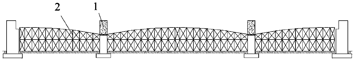
[0038] The second step is to install the bracket. See figure 1 , Use bracket cast-in-place construction starting zero block 1. According to the direction of the beam bridge, accurately release the erection range and vertical and horizontal spacing of the bracket 2 and clean the nearby gr...

Embodiment 2

[0044] In the second embodiment, a three-span prestressed concrete continuous box girder bridge with corrugated steel webs is taken as an example. A method for segmental bracket construction of a girder bridge has the following technical solutions:

[0045] The first step is to harden the foundation. Its bearing capacity and stability are sufficient to bear the self-weight load of the superstructure transmitted by the bracket.

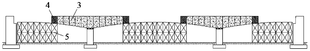
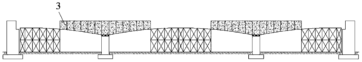
[0046] The second step is to install the bracket. See Picture 8 , Use bracket cast-in-place construction to start zero block 1. According to the direction of the beam bridge, accurately release the erection range and vertical and horizontal spacing of the bracket 2 and clean the nearby ground surface. Check the strength and stability of the bracket 2, and the calculation result should meet the requirements of the specification. Between the bridge piers and between the bridge piers and abutments, all supports 2 are arranged. Each support pole is equipped...


PUM


Abstract

The invention discloses a segment support construction method for a beam bridge. The segment support construction method includes the following steps: step 1, performing ground hardening; step 2, arranging all supports in each span, and prepressing the supports; step 3, mounting formworks, steel bars and the like on two sides of each pier segment by segment in a balanced way, pouring concrete, tensioning prestressed steel strands, and demounting the supports below each segment after tensioning is completed in each segment; step 4, when a maximum cantilever is used in construction, constructingside span cast-in-situ sections; step 5, mounting stiff skeletons for side span joining sections, joining side spans, and demounting the supports for the side span joining sections; step 6, cancelingtemporary consolidation of piers and beams, mounting stiff skeletons for middle span joining sections, joining middle spans, and demounting the supports for the middle span joining sections; step 3,tensioning external bundles, paving bridge floors and the like. The segment support construction method has the advantages of simplicity in operation, safety construction, high construction efficiencyand the like, and can be widely applied to the technical field of construction methods for short-pier beam bridges.

Description

Technical field [0001] The invention relates to the technical field of bridge construction methods. More specifically, the present invention relates to a construction method of a segment bracket of a beam bridge. Background technique [0002] In bridge construction, beam bridges are widely used. And with the rapid development of science and technology, construction technology is constantly improving, so the span of beam bridges is also getting larger and larger. For the construction of long-span girder bridges, currently known construction methods mainly include cantilever pouring method, mobile bracket method, and segmental prefabrication method. [0003] The cantilever pouring method is a method of constructing symmetrically section by section along the span of the bridge on the already built pier. Cantilever pouring is symmetrically pouring concrete on both sides of the bridge pier section by section. After the concrete reaches a certain strength, the prestressed beam is stre...

Claims


Application Information

Patent Timeline
IPC IPC(8): E01D21/00
Inventor 万水孙虎平杨湛郭红军李文清苏立超王海林郑会玺郑涛徐杰
Owner SOUTHEAST UNIV
Why Eureka
Try Eureka