
Method for dismantling and splicing cast-in-place reinforced concrete frame structure building components

A reinforced concrete and frame structure technology, which is applied in building construction, building material processing, construction, etc., can solve the problems of not being able to fully utilize the potential of abandoned buildings, building dumping and damage, and increasing the cost of waste, so as to avoid building materials. Generation of waste and dust, reduction of disposal, effects of land pollution reduction

Active Publication Date: 2019-05-24
CHINA UNIV OF MINING & TECH
View PDF5 Cites 2 Cited by
  • Summary
  • Abstract
  • Description
  • Claims
  • Application Information

AI Technical Summary

Problems solved by technology

This kind of treatment not only increases the cost of waste transportation and landfill, but also causes environmental pollution and waste of resources because it occupies a large amount of land.
Controlled blasting technology uses a series of blasting equipment to rationally use the explosion of explosives through rigorous calculations to cause buildings to fall and be destroyed. This dismantling measure is also devastating to the damage to building components and also brings a lot of waste of building materials. objects, unable to realize the full potential of abandoned buildings
In addition, during the blasting process, a large amount of dust will be generated, which will cause certain pollution to the environment.
[0004] It can be seen that whether it is mechanical demolition or controlled blasting technology, the traditional demolition methods will completely destroy the structure, and will eventually cause environmental pollution and waste of resources.

Method used


Image

  • Method for dismantling and splicing cast-in-place reinforced concrete frame structure building components
  • Method for dismantling and splicing cast-in-place reinforced concrete frame structure building components
  • Method for dismantling and splicing cast-in-place reinforced concrete frame structure building components

Examples


Embodiment

[0058] Embodiment: dismantling cast-in-place reinforced concrete frame structure building.

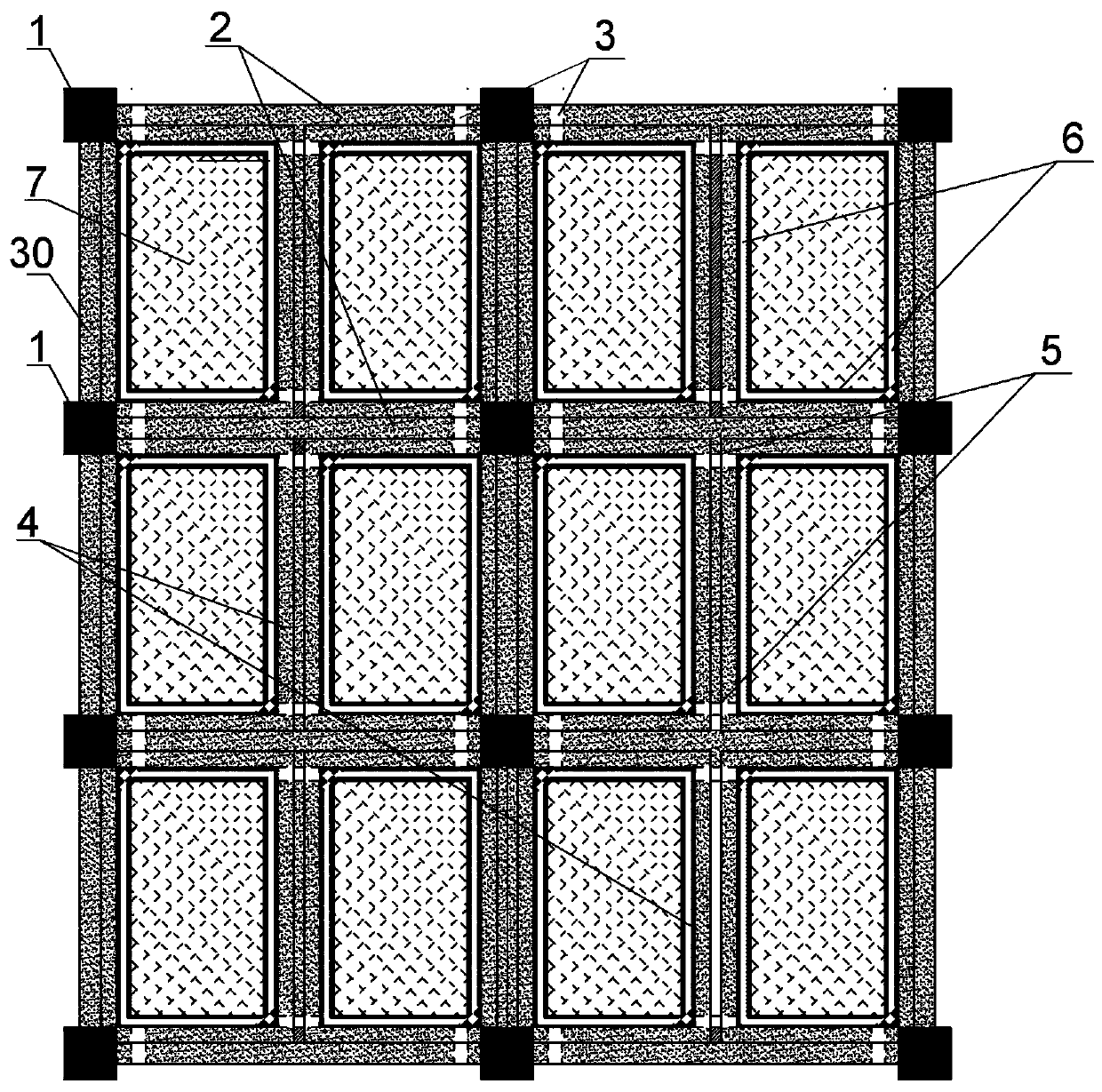
[0059] Step 1. Remove all walls, doors, windows and other non-load-bearing parts of the cast-in-place reinforced concrete frame structure building to be dismantled, leaving only the space force skeleton composed of beams, floors, and column load-bearing components. Depend on figure 1 As shown, in this embodiment, the spatial force frame contains three transverse frames, and each transverse frame is connected by four longitudinal connecting beams, and a secondary beam is arranged between the opposite longitudinal connecting beams, which is located in the middle of the longitudinal connecting beams.

[0060] Step 2. Divide the space force skeleton

[0061] The width direction of the house is set as the main force direction of the horizontal load, which is called the transverse direction, and the length direction perpendicular to it is recorded as the longitudinal direction. The entire s...


PUM


Abstract

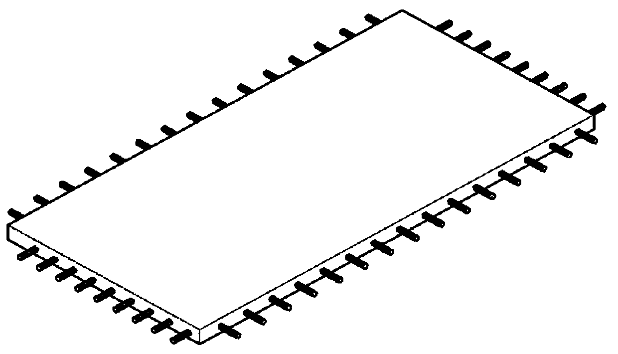
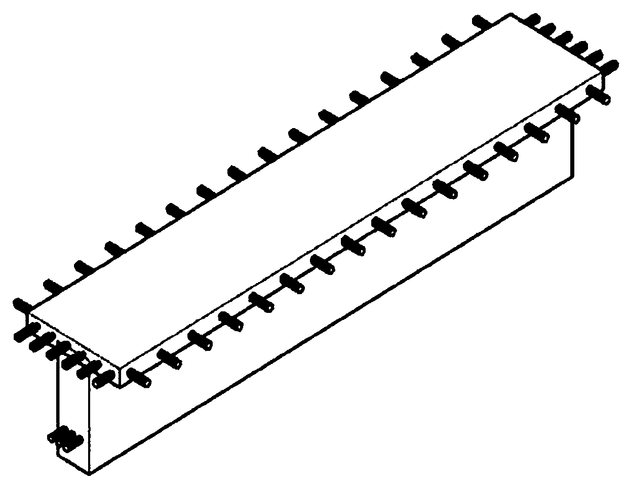
The invention discloses a method for dismantling and splicing cast-in-place reinforced concrete frame structure building components. The method includes dismantling a frame structure into floor slabs, secondary beams, longitudinal struts and horizontal frames in a main stress direction sequentially from top to bottom; dismantling the floor slabs by marking out dismantling strips along the peripheries of the floor slabs, crushing and removing concrete within the range of the dismantling strips, and cutting off reinforcing steel bars from the middles of the dismantling strips while leaving butts of the reinforcing steel bars on the peripheries of the floor slabs and peripheral beams so as to facilitate connection during splicing; dismantling the secondary beams and the longitudinal struts sequentially in the same way; last, dismantling beams and columns of the horizontal frames along the middle disconnection positions into +-shaped, T-shaped and L-shaped joint units. The components andthe joint units can be obtained by dismantling according to the method and can be spliced into a building frame like modular furniture, and accordingly relocation of buildings is realized.

Description

technical field [0001] The invention relates to a dismantling and assembling method of a frame structure building component, specifically a dismantling and assembling method of a cast-in-place reinforced concrete frame structure building component, which belongs to the dismantling of a building structure and the recycling technology of a building field. Background technique [0002] With the acceleration of industrialization and urbanization in our country, in the process of urban transformation, there are often contradictions between existing buildings and urban planning. Many buildings have to be demolished due to planning reasons. Among these buildings to be demolished There are a large number of frame structure buildings, and a considerable part of these frame structure buildings have not been built for a long time and still have great use value. Simple demolition will not only cause a lot of waste of resources, but also require a long construction period, and at the sa...

Claims


Application Information

Patent Timeline
Patent Type & Authority Applications(China)
IPC IPC(8): E04G21/14E04G23/08
Inventor 姬永生时方鸣郭煜诚陈鑫冰严久鑫徐之山陈豪周样梅
Owner CHINA UNIV OF MINING & TECH
Learn More