Microfluidic device for automatic quantitative distribution, collection and detection and using method of microfluidic device

A microfluidic device and quantitative distribution technology, applied in chemical instruments and methods, laboratory containers, biological tests, etc., can solve the problems of affecting test results, unable to quantitatively collect sweat electrolytes, and easy evaporation of sweat, etc., to achieve simplified Complexity, ease of preparation integration and automation, and the effect of increasing detection accuracy

Inactive Publication Date: 2019-05-28
XIANGTAN UNIV
View PDF12 Cites 7 Cited by
  • Summary
  • Abstract
  • Description
  • Claims
  • Application Information

AI Technical Summary

Problems solved by technology

Such as Jungil Choi et al. in 2018 Applied Sciences and Engineering The epidermal microfluidics mentioned in the Skin-interfaced systems for sweat collection and analytics published in the journal is an open microfluidic device that collects sweat in real time to measure blood sugar, but sweat evaporates easily, which affects the test results, and cannot Quantitative Sweat Collection and Electrolyte Detection in One Microfluidic Channel

Method used


Image

  • Microfluidic device for automatic quantitative distribution, collection and detection and using method of microfluidic device
  • Microfluidic device for automatic quantitative distribution, collection and detection and using method of microfluidic device
  • Microfluidic device for automatic quantitative distribution, collection and detection and using method of microfluidic device

Examples


Embodiment 1

[0064] Hybrid microfluidic automatic quantitative distribution, collection and detection device

[0065] 1.1 Structure of the device

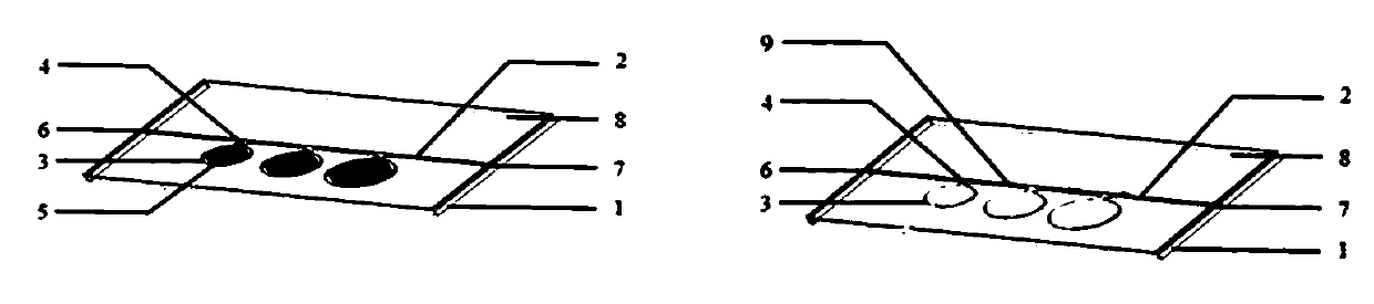
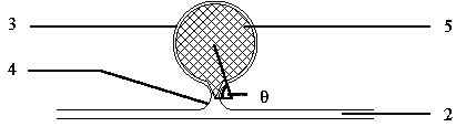
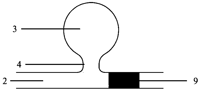
[0066] The structure of a mixed microfluid for implementing the above-mentioned automatic quantitative distribution, collection and detection provided by the present invention is as follows: figure 1 As shown, it consists of a substrate 1, a microfluidic channel 2, a side microfluidic chamber 3 located on one side of the microfluidic channel and communicating with it, a valve 4 connecting the microfluidic channel and the side microfluidic chamber, and filter paper (method 1) 5 , a fluid inlet 6, a fluid outlet 7, a cover plate 8 and a hydrophobic region (method 2) 9; wherein, the depth of the side microfluidic cavity 3 is greater than the depth of the microfluidic channel 2. figure 1 The left picture shows the automatic quantitative distribution, collection and detection device prepared by method one; figure 1 The picture on the right show...

Embodiment 2

[0082] Hybrid Microfluidic Detection of Hydrogen Peroxide Concentration

[0083] (1) Take 5 μl of potassium iodide in eight different concentrations of 0.06M, 0.05M, 0.045M, 0.4M, 0.035M, 0.03M, 0.025M, 0.01M, and 0.006M, and drop them into the Figure 7 On the filter paper 5 in the eight side microfluidic chambers 3 on the substrate 1 shown, the combination of the side microfluidic chambers 3 and the filter paper 5 is selected Image 6 In the combination method shown on the left, the valves 4 are not exactly the same size. Then, the substrate 1 and cover plate 8 loaded with potassium iodide filter paper 5 can be obtained by using the encapsulation method of the mixed microfluidic device in Method 1 of Embodiment 1 to obtain the mixed microfluid. Inject hydrogen peroxide of unknown concentration into the micro-flow channel 2 with a micro-injection pump, and the hydrogen peroxide will quickly enter different side micro-flow chambers 3 one by one, and the potassium iodide reage...

Embodiment 3

[0087] A device for urine analysis

[0088] like Figure 9 A schematic plan view of a mixed microfluidic device for detecting multiple components of urine is shown. Urine enters the microfluidic channel 2 from the fluid inlet 6, and when it flows through the side microfluidic cavity 3, the urine enters the side microfluidic channel through the capillary force of the filter paper. The microfluidic chamber 3 reacts with the corresponding reagent on the filter paper 5. At this time, the filter paper 5 can be selected as whatman4, which quickly absorbs liquid. When the liquid fills the side microfluidic chamber 3, the liquid in the side microfluidic chamber 3 will no longer After entering the microfluidic channel 2, the liquid on the microfluidic channel 2 will continue to flow on the microfluidic channel 2 and enter the next side microfluidic chamber 3. The reagents in each side microfluidic chamber 3 are different, and the combined sensor can simultaneously Accurate detection o...


PUM


Abstract

The invention discloses a microfluidic device for automatic quantitative distribution, collection and detection and a using method of the microfluidic device. The device realizes automatic quantitative distribution, collection and detection by changing local hydrophilicity/hydrophobicity. The first method comprises the step that hydrophilic materials such as porous media are added into microfluidic cavities, and valves corresponding to the hydrophilic materials are additionally arranged in the microfluidic cavities; and the second method comprises the step that hydrophobic treatment is conducted at the specific location of a microfluidic channel. The microfluidic device comprises a base, a cover plate, a fluid inlet, a fluid outlet, the microfluidic channel, side microfluidic cavities anda valve, sample liquid in the microfluidic device enters the side microfluidic cavities quantitatively, according to the characteristic of selective flowing of the liquid in a hydrophobic area and a hydrophilic area, the liquid in each cavity does not interfere with each other, whether detecting reagents are added into the side microfluidic cavities or not is decided according to the needs, and thus prepared sample liquid is automatically and quantitatively distributed, collected and detected. The microfluidic device for automatic quantitative distribution, collection and detection and the using method of the microfluidic device can be applied to a micro-biochemical reactor and a device laboratory.

Description

technical field [0001] The invention relates to a microfluidic device for automatic quantitative distribution, collection and detection and a use method, which can be applied to microbial reactors and device laboratories. Background technique [0002] In recent years, microfluidic devices, as a new technology platform, have received widespread attention in the fields of chemistry, biology, and medicine. With advantages such as the integration of various operating units, the microfluidic system has unparalleled advantages for various biological and chemical experiments. [0003] Epidermal microfluidics, paper-based microfluidics, and hybrid microfluidics all belong to the category of microfluidics. [0004] Epidermal microfluidics was proposed by the Rogers research group of Northwestern University in the United States, which mainly refers to flexible microfluidic devices that can be used on human epidermis. Epidermal microfluidic devices can capture, deliver, and store mic...

Claims


Application Information

Patent Timeline
Patent Type & Authority Applications(China)
IPC IPC(8): B01L3/00B01J19/00G01N21/78G01N33/50
Inventor 王秀锋陈玲张迎雪陈尚达钱飞
Owner XIANGTAN UNIV
Why Eureka
Try Eureka