Electrolytic cell with uniform vertical inflowing feeding

An electrolytic cell and a uniform technology, applied in the field of electrolytic cells with uniform vertical inflow feeding, can solve the problems of unfavorable anode mud particle settlement, uneven liquid flow distribution, and affecting the quality of the cathode, so as to facilitate high current density electrolysis production and eliminate concentrated The effect of poor polarization and improved efficiency

Pending Publication Date: 2019-05-28
CENT SOUTH UNIV
View PDF6 Cites 2 Cited by
  • Summary
  • Abstract
  • Description
  • Claims
  • Application Information

AI Technical Summary

Problems solved by technology

Among them, the liquid inlet mode of bottom in and top out, the flow direction of the electrolyte is just opposite to the direction of anode slime particle settlement, which is not conducive to the settlement of anode slime particles to a certain extent; The liquid circulation direction is consistent with the sedimentation mode of the anode slime particles, but this way of concentrating one end of the liquid into the liquid will cause uneven distribution of the liquid flow. Excessive power consumption will also cause agitation of the anode slime, affecting the quality of the cathode during the electrolysis process

Method used


Image

  • Electrolytic cell with uniform vertical inflowing feeding
  • Electrolytic cell with uniform vertical inflowing feeding
  • Electrolytic cell with uniform vertical inflowing feeding

Examples


Embodiment 1

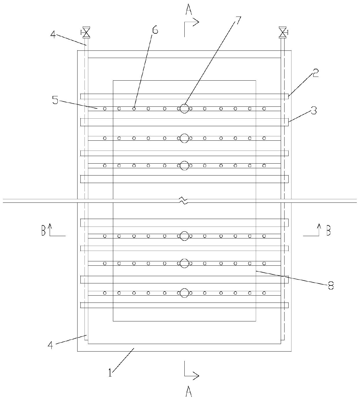
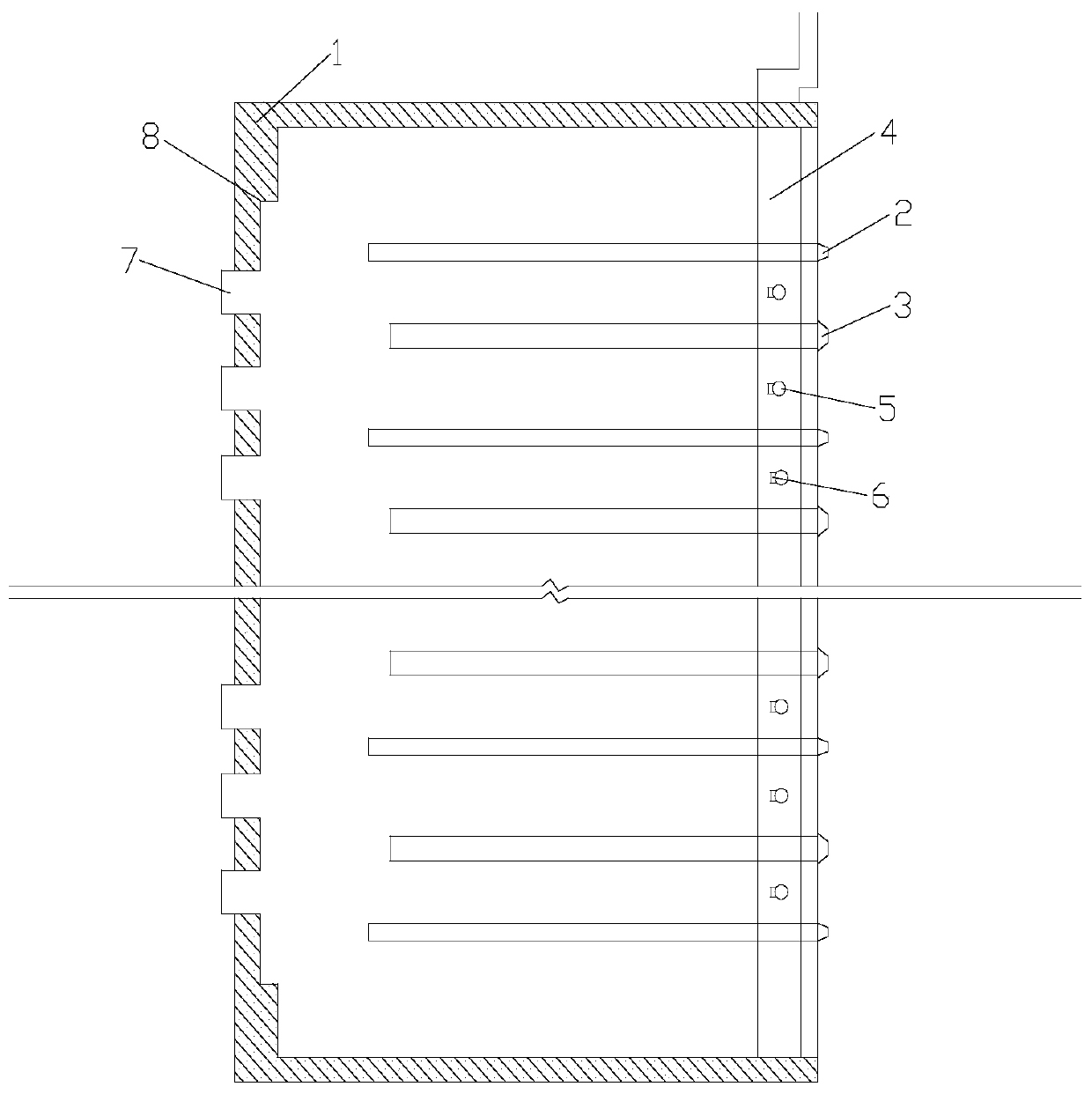
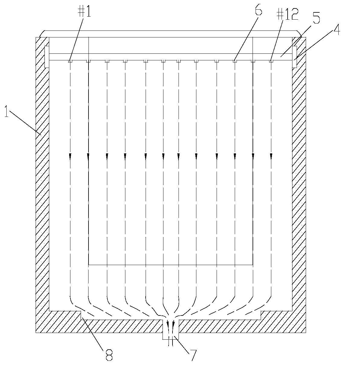
[0021] An electrolytic cell with uniform vertical inflow feeding, such as figure 1 , figure 2 , image 3 As shown, it includes an electrolytic cell body 1, a plurality of cathode plates 2, a plurality of anode plates 3, a solution channel I4, a solution channel II 5, a plurality of liquid inlet nozzles 6, a plurality of liquid outlet nozzles 7, and a rectangular Groove 8.

[0022] Such as image 3 As shown, the liquid inlet nozzles installed on the solution channel Ⅱ5 are respectively named #1 to #12 from left to right. In this embodiment, a single electrolytic cell is used as an object, and a total of 12 liquid inlet nozzles #1-#12 are used to feed liquid at the same time. On this basis, the orthogonal experiments with two factors and two levels were carried out. Among them, current density: 240 A / m 2 ,300A / m 2 ; Electrolyte flow rate: 11ml / min, 22ml / min. The period of each experiment is two days. After the experiment, ICP is used to detect and analyze the content of...

Embodiment 2

[0026] A total of 10 liquid inlet nozzles #2-#11 were used as solution inlets to feed liquid at the same time, and the condition experiment in Example 1 was repeated, and the analysis results are shown in Table 2.

[0027] Impurity content in the cathode copper of table 2 (unit: ppm)

[0028]

Embodiment 3

[0030] Using #3-#10, a total of 8 liquid inlet nozzles as solution inlets to feed liquid at the same time, repeat the above experiment, and the analysis results are shown in Table 3.

[0031] Impurity content in the cathode copper of table 3 (unit: ppm)

[0032]


PUM


Abstract

The invention discloses an electrolytic cell with uniform vertical inflowing feeding. The electrolytic cell comprises a cell body; the cell body is provided with multiple cathode plates and anode plates which are alternately arranged at intervals in a length direction of the cell body in a crossing manner; the two sides of the top of the cell body are provided with solution channels I respectively; multiple solution channels II are arranged between the solution channels I on the two sides at intervals in a length direction in the crossing manner; and the two ends of the solution channel II arecommunicated with the solution channels I on the corresponding sides respectively; each solution channel II is uniformly provided with multiple liquid inlet nozzles at intervals in the length direction; and the bottom of the cell body is provided with a liquid outlet nozzle. The electrolytic cell with the structure has the advantages that concentration polarization can be eliminated, high-currentdensity electrolytic production is facilitated, the circulation amount of an electrolyte is effectively lowered, sedimentation of anode mud is facilitated, and the cathode quality is improved.

Description

technical field [0001] The invention relates to the technical field of metal electrolysis, in particular to an electrolytic cell with uniform vertical inflow feeding. Background technique [0002] During the copper smelting process, the copper products obtained by pyro-refining contain a large amount of impurities. In order to obtain high-quality copper products, it is necessary to perform electrolytic purification on the copper products produced in the pyro-refining process. The traditional copper electrolysis technology is to cast the copper obtained in the fire refining step into an anode plate, and use a pure copper sheet as a cathode plate, and place the two in an electrolytic cell where the electrolyte flows slowly. By controlling certain electrolytic process parameters, the target metal ions are continuously dissolved from the anode into the electrolyte, and then diffused to the cathode for electrolytic deposition and precipitation, thereby achieving the effect of me...

Claims


Application Information

Patent Timeline
Patent Type & Authority Applications(China)
IPC IPC(8): C25C1/12C25C7/00
CPCY02P10/20
Inventor 曾伟志刘山杨建广胡辉李垦李博
Owner CENT SOUTH UNIV
Why Eureka
Try Eureka