Cascade-heating multimode-coupled heat pump water heater

A heat pump water heater and cascade heating technology, applied in the field of heat pumps, can solve the problems of large power consumption, waste of hot water effective energy, and large heat exchange temperature difference, so as to improve capacity and cycle efficiency, improve heat exchange efficiency, and reduce exchange rate. The effect of thermal temperature difference

Active Publication Date: 2019-05-28
ZHEJIANG UNIV OF TECH
View PDF6 Cites 3 Cited by
  • Summary
  • Abstract
  • Description
  • Claims
  • Application Information

AI Technical Summary

Problems solved by technology

However, several important reasons for the low efficiency of traditional direct-heating heat pump water heaters are the large heat transfer temperature difference between the refrigerant and cold water, as well as throttling losses and compressor losses. Therefore, heat pump water heaters also need Consumes a lot of power, and the efficiency is not ideal enough, so improving its electrical efficiency is an important improvement direction
Existing heat pump water heaters can only heat water to a very high temperature and store it in the water tank. When users use hot water at a lower temperature, they can only use it after mixing hot water with high temperature from the water tank and mixing it with cold water. This process wastes the available energy in the hot water ( ), resulting in a large entropy production, reducing energy utilization, and having a single hot water temperature that cannot quickly meet the user's needs for different water temperatures; and when the heat pump system detects that the water temperature has dropped, it will automatically start to process the water in the entire water tank Hydronic heating, which is a waste of energy and hot water that cannot be quickly replenished to the user's desired temperature

Method used


Image

  • Cascade-heating multimode-coupled heat pump water heater
  • Cascade-heating multimode-coupled heat pump water heater
  • Cascade-heating multimode-coupled heat pump water heater

Examples


Embodiment 1

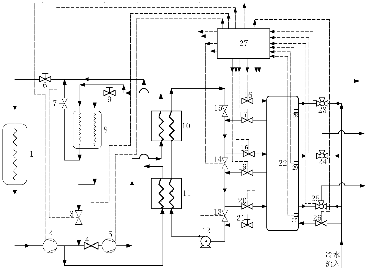
[0021] refer to figure 1 , a heat pump water heater with cascade heating and multi-mode coupling. Valve 4, second compressor 5, first expansion valve 6, second expansion valve 7, regenerator 8, third expansion valve 9, second condenser 10, first condenser 11, water pump 12, third stop Valve 13, fourth stop valve 14, fifth stop valve 15, sixth stop valve 16, seventh stop valve 17, eighth stop valve 18, ninth stop valve 19, tenth stop valve 20, flow regulating valve 21, Water tank 22, first water mixing valve 23 (with flow sensor), second water mixing valve 24 (with flow sensor), third water mixing valve 25 (with flow sensor), eleventh stop valve 26, control system 27, A first temperature sensor 28 , a second temperature sensor 29 and a third temperature sensor 30 .

[0022]The inlet of the first compressor 2 is connected to the outlet of the evaporator 1 through a pipeline, and the outlet of the first compressor 2 is respectively connected to the outlet of the first shut-off ...

Embodiment 2

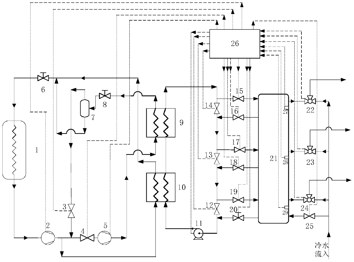
[0029] refer to figure 2 , a heat pump water heater with cascade heating and multi-mode coupling. Valve 4, second compressor 5, first expansion valve 6, gas-liquid separator 7, second expansion valve 8, second condenser 9, first condenser 10, water pump 11, third stop valve 12, fourth Stop valve 13, fifth stop valve 14, sixth stop valve 15, seventh stop valve 16, eighth stop valve 17, ninth stop valve 18, tenth stop valve 19, flow regulating valve 20, water tank 21, first Mixing valve 22 (with flow sensor), second mixing valve 23 (with flow sensor), third mixing valve 24 (with flow sensor), eleventh stop valve 25, control system 26, first temperature sensor 27 , the second temperature sensor 28 and the third temperature sensor 29.

[0030] The inlet of the first compressor 2 is connected to the outlet of the evaporator 1 through a pipeline, and the outlet of the first compressor 2 is respectively connected to the outlet of the first shut-off valve 3, the inlet of the second...

Embodiment 3

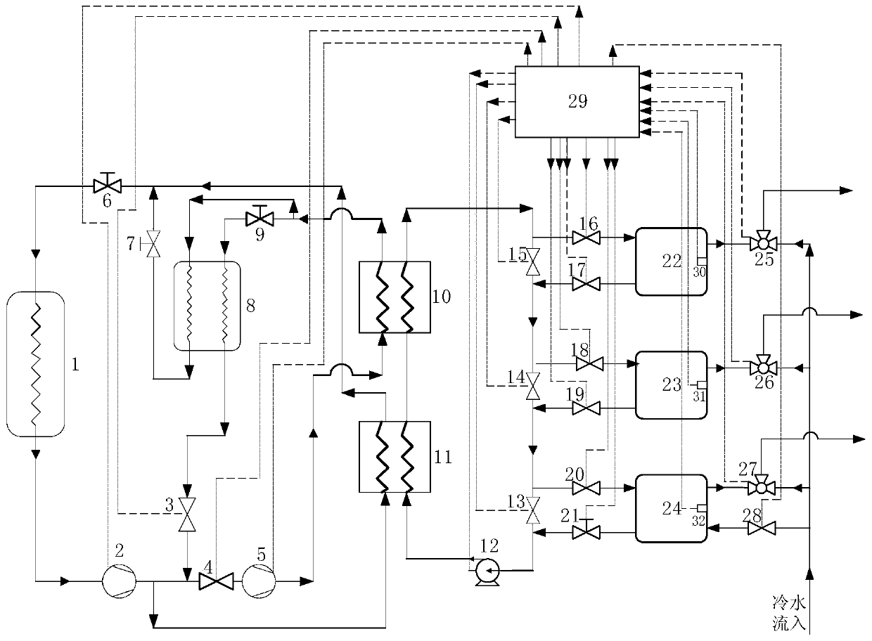
[0037] refer to image 3 , a cascade heating multi-mode coupling heat pump water heater, the water heater is a cascade heating multi-mode coupling multi-tank double compression heat pump water heater, including an evaporator 1, a first compressor 2, a first shut-off valve 3, and a second shut-off valve 4. Second compressor 5, first expansion valve 6, second expansion valve 7, regenerator 8, third expansion valve 9, second condenser 10, first condenser 11, water pump 12, third stop valve 13. The fourth stop valve 14, the fifth stop valve 15, the sixth stop valve 16, the seventh stop valve 17, the eighth stop valve 18, the ninth stop valve 19, the tenth stop valve 20, the flow regulating valve 21, the One water tank 22, the second water tank 23, the third water tank 24, the first water mixing valve 25 (with flow sensor), the second water mixing valve 26 (with flow sensor), the third water mixing valve 27 (with flow sensor), The eleventh stop valve 28 , the control system 29 , t...


PUM


Abstract

The invention relates to a cascade-heating multimode-coupled heat pump water heater which comprises an evaporator, a first compressor, a first stop valve, a second stop valve, a second compressor, a first expansion valve, a second condenser, a first condenser, a water pump, a third stop valve, a fourth stop valve, a fifth stop valve, a sixth stop valve, a seventh stop valve, an eighth stop valve,a ninth stop valve, a tenth stop valve, a flow regulating valve, a water tank, a first water mixing valve, a second water mixing valve, a third water mixing valve and an eleventh stop valve. Accordingto the cascade-heating multimode-coupled heat pump water heater, two-stage compression and two-stage throttling heat pump cycle is switched in multiple modes to independently heat multiple stratifiedzones with different temperatures in the water tank; by switching the different stop valves, the separate heating mode for the stratified zones with different setting temperatures is realized in different coupling modes, and the mode of taking water from the stratified zones with different temperatures is adopted. The heat production efficiency is high.

Description

technical field [0001] The invention belongs to the field of heat pumps and relates to a heat pump water heater. Background technique [0002] With the gradual recognition of the market and the support of national policies, air source heat pump water heaters have been widely promoted, and users pay special attention to water comfort and energy saving. However, several important reasons for the low efficiency of traditional direct heat pump water heaters are the large heat transfer temperature difference between the refrigerant and the cold water, as well as throttling losses and compressor losses. Therefore, heat pump water heaters also need It consumes a lot of electric energy, and the efficiency is not ideal enough, so improving its electric efficiency is an important improvement direction. Existing heat pump water heaters can only heat water to a very high temperature and store it in the water tank. When users use hot water at a lower temperature, they can only use it af...

Claims


Application Information

Patent Timeline
IPC IPC(8): F24H4/02F24H9/20F25B30/02F25B41/04F25B41/20F25B41/24F25B41/31
Inventor 徐英杰李恩腾蒋宁
Owner ZHEJIANG UNIV OF TECH
Why Eureka
Try Eureka