1000kv UHV Transformer Low Voltage Lead Disassembly Platform

A low-voltage lead, transformer technology, applied in switchgear, electrical components, etc., can solve the problems of inability to ensure the safety of personnel and equipment, slow operation process, time-consuming and laborious, etc., to reduce the risk of high-altitude work, stable standing space, and flexible structural design. Effect

Active Publication Date: 2020-05-08
国网河南省电力公司超高压公司 +1
View PDF8 Cites 2 Cited by
  • Summary
  • Abstract
  • Description
  • Claims
  • Application Information

AI Technical Summary

Problems solved by technology

According to the requirements of safety regulations, in order to avoid breaking the porcelain bottle, maintenance personnel are not allowed to directly climb the porcelain bottle; on the other hand, the capillary pipeline on the top of the transformer body is complicated, and there is not enough space to erect ladders or scaffolding
The above reasons make the on-site operation more difficult, not only cannot guarantee the safety of personnel and equipment, but also makes the disassembly and assembly of lead wires time-consuming and laborious, which affects the progress of the next work.
[0004] The existing lead wire removal method is relatively primitive, and insulation ladders, sleepers and other climbing or raising tools are often used to achieve the working height. On the porcelain bottle, use a sleeper horizontally to ride on these two vertical sleepers, and finally tie it up with a rope and fix it, and the maintenance personnel stand on the horizontal sleepers to perform operations; this type of method has the following shortcomings: first of all, personnel safety, In high-altitude operations, the safety of personnel cannot be guaranteed; the second is equipment safety. During the transportation of insulation ladders and sleepers to the transformer body, various pipelines may be touched. At the same time, during the process of fixing and climbing Both may damage the porcelain bottle and affect its insulation performance; the last is the work efficiency. When disassembling the lead wire, due to the heavy lead wire, two people are required to cooperate. The narrow position is not conducive to disassembly and assembly. The operation process is slow, time-consuming and laborious.
[0005] For example, the patent document whose publication number is CN102510013A discloses a box-type transformer maintenance platform, a supporting platform detachably connected to the transformer casing, and the patent document whose publication number is CN205081383U discloses a transformer high-altitude operation platform, the above two Although a standing platform is designed for the structure, the structure of the UHV transformer and the location of the low-voltage lead wires are very different from those of conventional transformers, and they cannot be used in a matching manner.

Method used


Image

  • 1000kv UHV Transformer Low Voltage Lead Disassembly Platform
  • 1000kv UHV Transformer Low Voltage Lead Disassembly Platform
  • 1000kv UHV Transformer Low Voltage Lead Disassembly Platform

Examples


Embodiment 1

[0056] The invention discloses a 1000kV ultra-high voltage transformer low-voltage lead wire disassembly platform, which includes an operation platform and a fixing component.

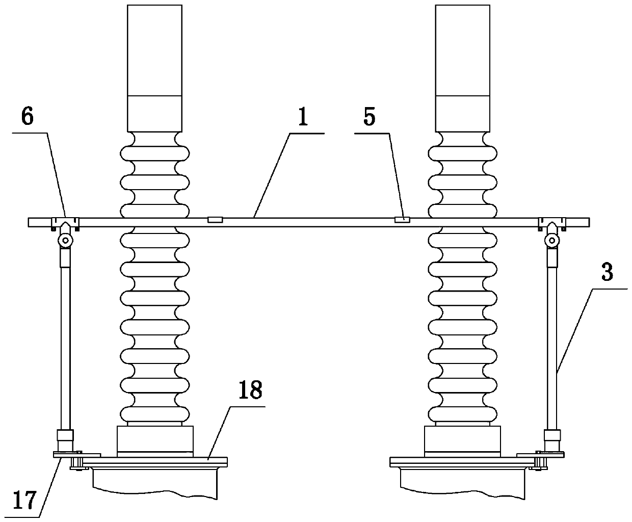
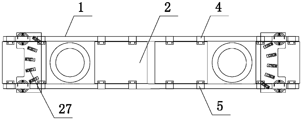
[0057] Such as figure 1 and figure 2 As shown, the work platform includes two horizontal bars 1 arranged in parallel, four foot boards 2 arranged between the two horizontal bars 1 for providing standing space, and two footboards 2 fixed on the two horizontal bars for providing vertical support. The four outriggers 3 on the crossbar 1; among them, the crossbar 1 and the outriggers 3 are made of epoxy resin fiberglass tubes, the footboard 2 is made of 3mm thick patterned aluminum plate, and the upper and lower ends of the footboard 2 are provided with silicon Rubber protective pad, one end of the pedal 2 is provided with a pedal sleeve 4 socketed with the crossbar 1, and the other end is provided with an arc-shaped clamping plate 5 clamped with the cross-bar 1, and the arc of the arc-shaped clamping pl...

Embodiment 2

[0062] The structure of this embodiment is basically the same as that of Embodiment 1, the difference is: as Figure 10 and 11 As shown, the crossbar 1 is a detachable structure, including a first rod body 28 and a second rod body 29, one end of the first rod body 28 is connected with a third connecting plate 30 through a first sleeve, and the third connecting plate 30 is connected to the first The sleeve is integrally formed, and the end surface of the third connecting plate 30 is provided with a through hole and four slots 9 evenly arranged around the through hole in the circumferential direction. One end of the second rod body 29 is provided with a fourth connecting plate 31 through the second sleeve. The four connecting plates 31 are integrally formed with the second sleeve, the fourth connecting plate 31 is provided with a through hole and four card protrusions 15 that are uniformly arranged around the through hole in the circumferential direction and match the card groov...

Embodiment 3

[0064] The structure of this embodiment is basically the same as that of Embodiment 1, the difference is: as Figure 12 As shown, two first clamping assemblies can be set on each transformer rising seat flange 18, and the first clamping assembly is positioned at the inner side of the two porcelain bottles; as Figure 13 As shown, two first clamping assemblies can also be arranged on the inner and outer sides of the porcelain bottle, that is, eight first clamping assemblies and eight legs 3 can be used together (the four on the front side are shown in the figure), stable Stronger.


PUM


Abstract

The invention belongs to the technical field of transformer substation operation and maintenance, and in particular relates to a low-voltage lead disassembling and assembling platform for a 1000kV extra-high voltage transformer. The working platform comprises two cross rods arranged in parallel, one or more pedals arranged between the two cross rods and used for providing standing space and a plurality of supporting legs fixed to the two cross rods and used for providing vertical supporting force. The problem that the low-voltage lead of the 1000kV extra-high voltage transformer is difficult to disassemble and assemble is solved, the personal and equipment safety is ensured, and meanwhile, the operation efficiency is improved.

Description

technical field [0001] The invention belongs to the technical field of substation operation and maintenance, in particular to a platform for disassembling and assembling low-voltage leads of 1000kV ultra-high voltage transformers. Background technique [0002] The 1000kV UHV transformer is the core equipment in the UHV substation. During the annual inspection of all substation equipment, the task of transformer maintenance is particularly important. Due to the high voltage level of the transformer, many difficulties will be encountered in on-site work, and the typical work content is the disassembly and assembly of low-voltage leads. [0003] The 1000kV transformer has high requirements on the insulation level of the material. Its low-voltage bushing is much higher than that of the 500kV transformer. The part of the porcelain bottle above the rising seat alone reaches 1.9 meters. In the disassembly and assembly of low-voltage lead wires in recent years, it is difficult for ...

Claims


Application Information

Patent Timeline
Patent Type & Authority Patents(China)
IPC IPC(8): H02B3/00
Inventor 王校丹麻森曲欣刘亚林张庆军李洪波王长义李纯刘春张海涛
Owner 国网河南省电力公司超高压公司
Why Eureka
Try Eureka