
Sludge quick-consolidation construction machinery equipment capable of dissolving grease

A technology of construction machinery and equipment, applied in the direction of dewatering/drying/concentrating sludge treatment, etc., can solve the problems of inability to meet the requirements of use, blocking the water outlet gap between the movable ring and the fixed ring, and water inflow resistance, and achieve the ability to avoid sludge treatment. Reduce, improve work efficiency and quality, promote the effect of grease discharge

Inactive Publication Date: 2019-06-04
陈丽玉
View PDF0 Cites 0 Cited by
  • Summary
  • Abstract
  • Description
  • Claims
  • Application Information

AI Technical Summary

Problems solved by technology

[0002] With the development of social economy and the acceleration of urbanization, the industrial wastewater and domestic wastewater produced by urban sewage treatment plants are gradually increasing, and the accompanying sludge is also increasing sharply. If the sludge is not properly treated, it will cause serious environmental pollution. Therefore, sludge rapid consolidation equipment is usually used to recycle sludge, but the current technical considerations are not perfect, and it has the following disadvantages: there is a large amount of oily wastewater in industrial wastewater and domestic wastewater mixed with sludge, which enters sludge treatment equipment for separation After opening, there will be a small amount of grease adsorbed on the surface of the movable ring and the fixed ring, which will gradually increase over time. If it is not cleaned in time, it will block the water outlet gap between the movable ring and the fixed ring over time, which will seal the sludge outlet water. There is a filter press central area in the equipment, which cannot be discharged in time. At the same time, it will also cause a certain resistance to the water intake, which directly leads to a reduction in the sludge treatment capacity and cannot meet the use requirements.

Method used


Image

  • Sludge quick-consolidation construction machinery equipment capable of dissolving grease
  • Sludge quick-consolidation construction machinery equipment capable of dissolving grease
  • Sludge quick-consolidation construction machinery equipment capable of dissolving grease

Examples


Embodiment

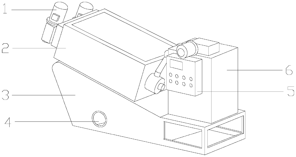
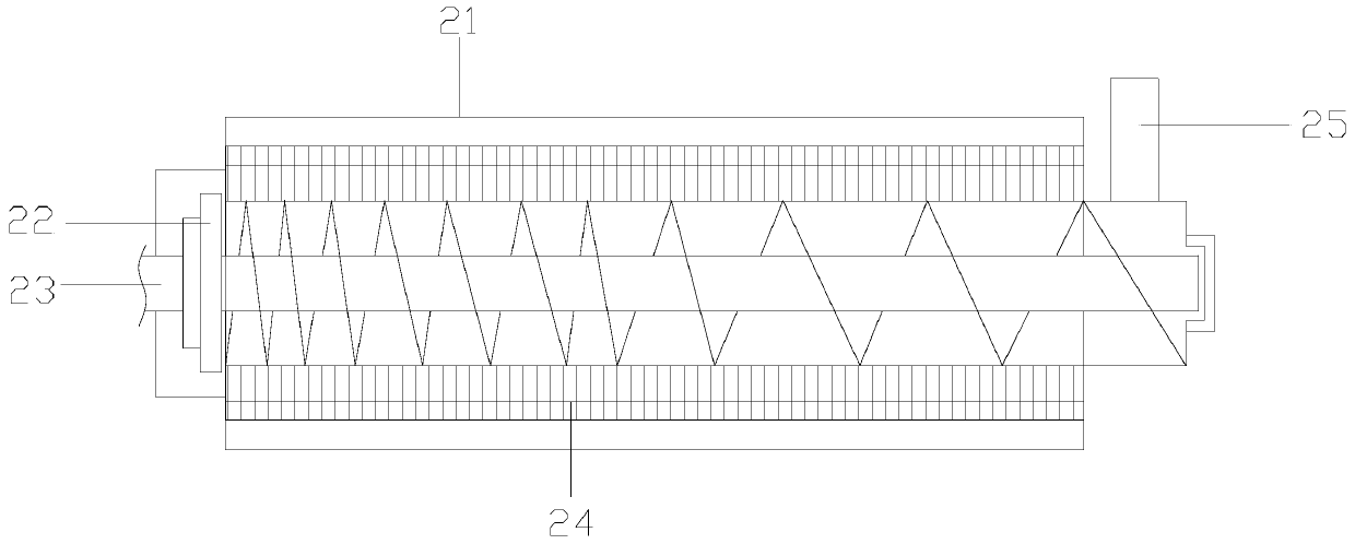
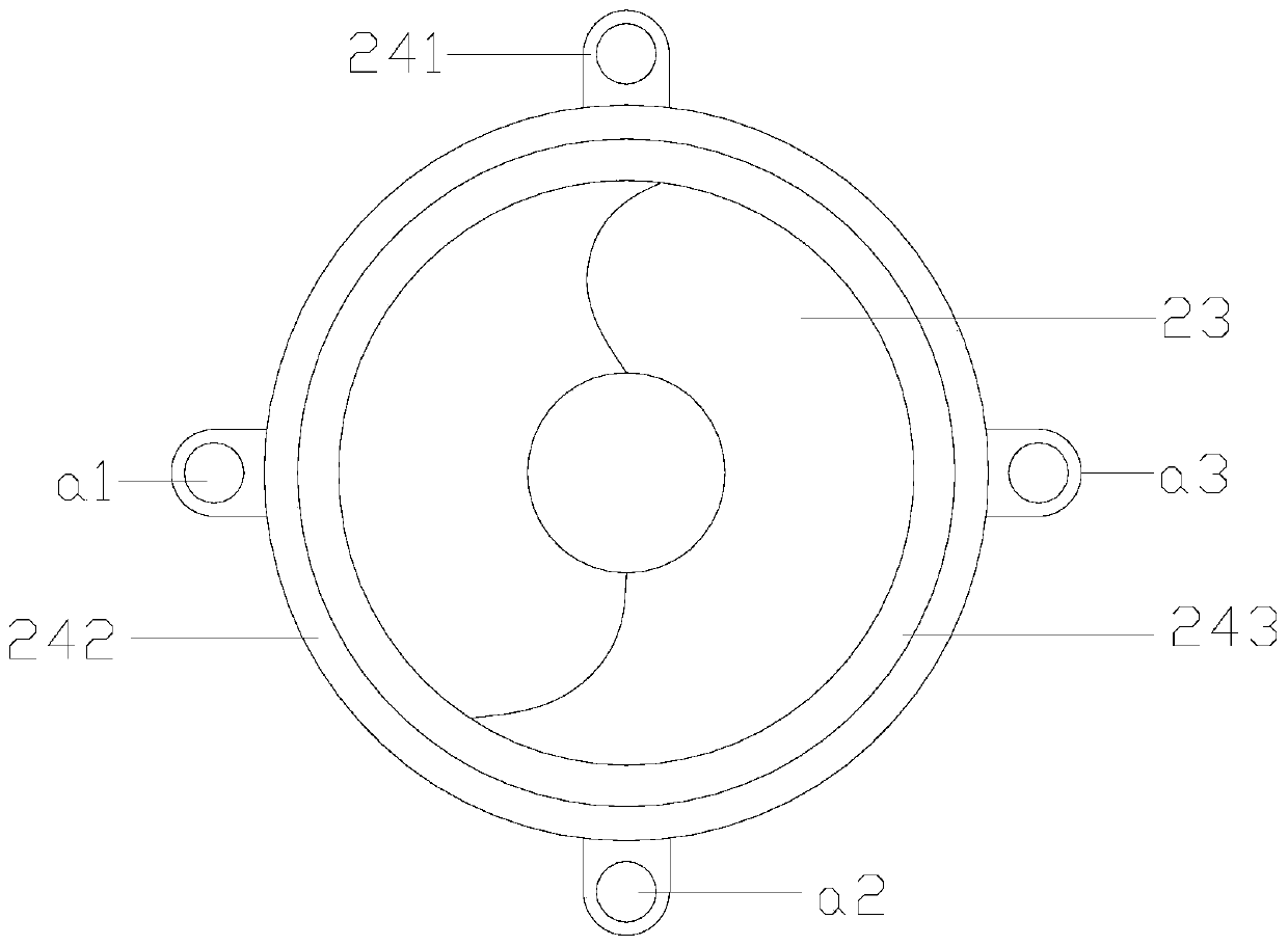
[0028] see Figure 1-Figure 2 , the present invention provides a sludge rapid consolidation construction machinery equipment capable of dissolving grease, the structure of which includes a drive motor 1, a dehydration consolidation mechanism 2, an equipment fixing seat 3, a filtrate outlet 4, an electric controller 5, and a flocculation stirring Mechanism 6, the equipment fixing seat 3 is horizontally installed on the ground, the bottom surface of the flocculation stirring mechanism 6 and the upper surface of the equipment fixing seat 3 are fixed together by bolts, the back of the electric controller 5 is connected to the flocculation stirring mechanism 6 The fronts are close together, the bottom surface of the dehydration consolidation mechanism 2 is welded to the left end of the upper surface of the equipment fixing seat 3, and the drive motor 1 is provided with three mechanical connections with the dehydration consolidation mechanism 2 and the flocculation stirring mechanism...


PUM


Abstract

The invention discloses sludge quick-consolidation construction machinery equipment capable of dissolving grease. The structure of the equipment comprises a driving motor, a dewatering and consolidation mechanism, an equipment fixing seat, a filtrate water outlet, an electric controller, and a flocculation and stirring mechanism. After the sludge quick-consolidation construction machinery equipment is used for a long period of time and when there is residual grease on the fixed ring and the movable ring and blocking happens, a grease dissolution structure can be utilized to heat grease and rapidly melt and discharge the grease; and an aeration device can promote the discharge of grease by blowing air such that the residual grease can be removed more thoroughly. Thereby, decrease of the sludge treatment capacity due to grease blocking is avoided, and work efficiency and quality of sludge dewatering are improved.

Description

technical field [0001] The invention relates to the field of rapid dehydration equipment, in particular to construction machinery and equipment for rapid consolidation of sludge that can dissolve grease. Background technique [0002] With the development of social economy and the acceleration of urbanization, the industrial wastewater and domestic wastewater produced by urban sewage treatment plants are gradually increasing, and the accompanying sludge is also increasing sharply. If the sludge is not properly treated, it will cause serious environmental pollution. Therefore, sludge rapid consolidation equipment is usually used to recycle sludge, but the current technical considerations are not perfect, and it has the following disadvantages: there is a large amount of oily wastewater in industrial wastewater and domestic wastewater mixed with sludge, which enters sludge treatment equipment for separation After opening, there will be a small amount of grease adsorbed on the s...

Claims


Application Information

Patent Timeline
IPC IPC(8): C02F11/12
Inventor 陈丽玉
Owner 陈丽玉
Learn More