Rotary engine

A kind of engine, rotary technology, applied in the direction of combustion engine, machine/engine, internal combustion piston engine, etc., can solve the problems of complex structure, loss of heat energy, inability to create basic adjustment parts, etc.

Active Publication Date: 2019-06-04
台州市波发动力科技有限公司
View PDF5 Cites 0 Cited by
  • Summary
  • Abstract
  • Description
  • Claims
  • Application Information

AI Technical Summary

Problems solved by technology

Due to the large space of storage tanks and pipelines, the synchronous rotation of the working cylinder and the compression cylinder in a single working cycle cannot create the basic adjustment suitable for the high-pressure and high-temperature working of the engine before ignition. At the same time, the compression produces high temperature that is conducive to ignition In the process of gas storage and transportation, it is emitted in a large amount, and it is impossible to realize the high-pressure and high-temperature cooperation of instant power ignition. It is equipped with a cooling system, which means that this structure will lose a lot of heat energy during operation. It has a lubrication and sealing system, which also shows that its structure is also complicated. , he only mentioned in the description of the background technology of the Chinese patent No. 201110384323.1 0002 that the Chinese invention patent 00136274.7 discloses a design structure of a double-rotating-piston counter-rotating engine, which improves the intake pressure and isolates it. There are still some improvements made by the film and spacers, but there are still deficiencies.

Method used


Image

  • Rotary engine
  • Rotary engine
  • Rotary engine

Examples


Embodiment 1

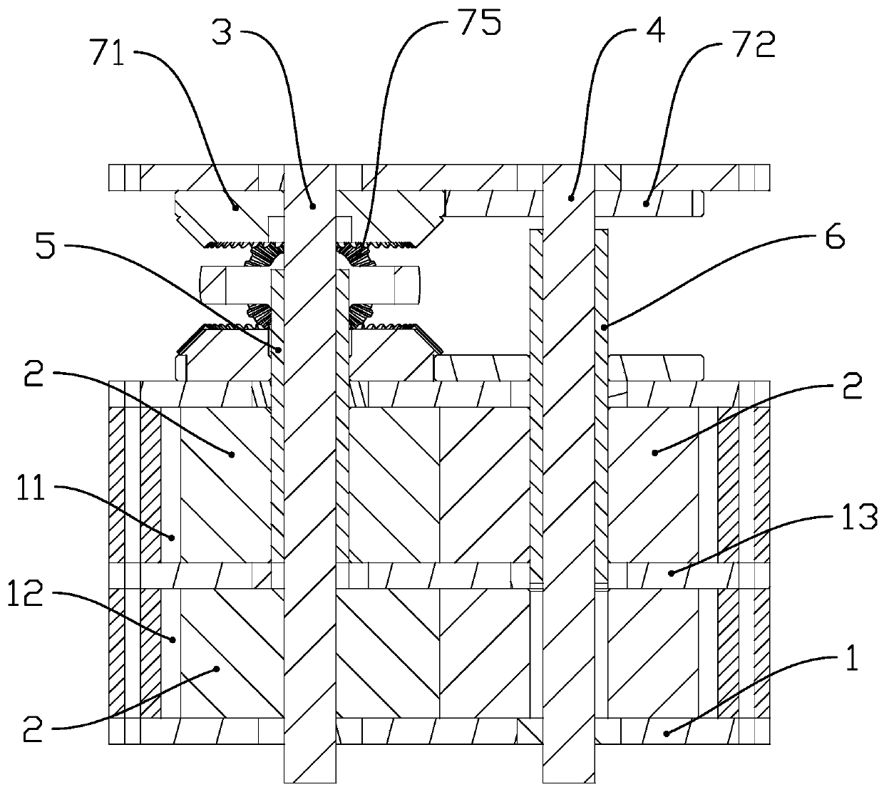
[0056] Each piston 2 is provided with a pair of adjacently arranged grooves 21 and projections 22, an air inlet 15 is provided on the side wall away from the through hole 14 in the upper rotary chamber 11, and an air inlet 15 is provided on the side wall far away from the through hole 14 in the upper rotary chamber 12, and the inner wall of the lower rotary chamber 12 is close to the through hole 14. The side wall of the main body 1 is provided with an oil supply device 17 and an ignition device 18; the side wall of the main body 1 is provided with an oil supply hole 17 connected with the oil supply device and an electrode hole 18 connected with the ignition device, and the electrode hole 18 is connected with the lower rotating chamber. 12 communicates, and the oil supply pipe connecting the oil supply hole 17 and the side wall of the through hole 14 is provided on the partition plate 13; Chamfering, the inner edge of the through hole 14 coincides with the lower edge of the cha...

Embodiment 2

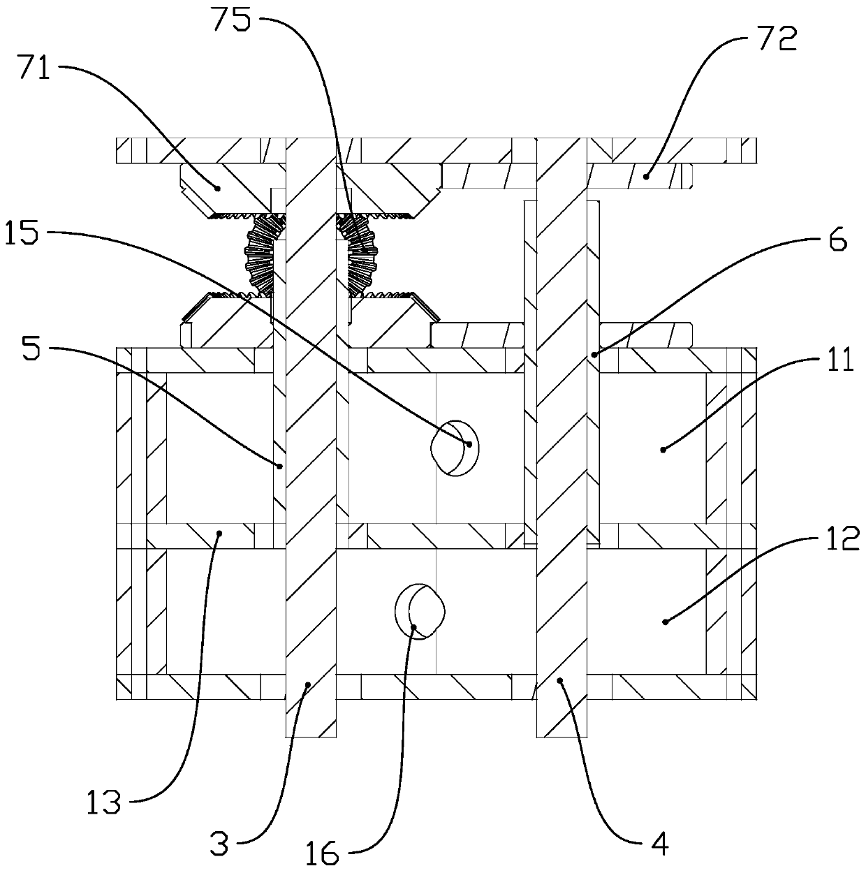
[0058] Each piston 2 is provided with two pairs of grooves 21 and projections 22 at intervals of 180 degrees. When the projection 22 at the front end of the rotation direction in the lower rotating chamber 12 is about to break away from the side wall of the lower rotating chamber 12, the other piston 2 On the dividing plate 13 of the groove 21 matched with the protrusion 22, a through hole 14 connecting the upper rotating chamber 11 and the lower rotating chamber 12 is provided. The two through holes 14 are centrally symmetrical about the dividing plate 13, and the upper rotating chamber 11 and the left and right sides of the lower rotating chamber 12 are all symmetrically provided with an air inlet 15 and an exhaust port 16, and each exhaust port 16 is located on the front side of the corresponding piston 2 in the direction of rotation, and each air inlet 15 are all arranged on the rear side of the corresponding piston 2 in the direction of rotation. The side wall of the main ...


PUM


Abstract

The invention provides a rotary engine, and belongs to the technical field of engines. The method solves the technical problems that an existing engine is low in heat energy conversion efficiency andthe like. An upper rotary chamber and a lower rotary chamber of a main body of the rotary engine are separated by a partition plate provided with a through hole, the upper rotary chamber and the lowerrotary chamber are both provided with two pistons, the upper piston and the lower piston are coaxially arranged and are opposite in rotation direction, the rotating directions of the two adjacent pistons are opposite, the side surfaces of the two pistons are in contact sealing, at least one pair of adjacently arranged grooves and a convex block is arranged on the side wall of each piston, the outer side surface of the convex block can abut against the inner side wall of the upper rotary chamber or the inner side wall of the lower rotary chamber to form a relatively sealed cylinder cavity, when the piston of the upper rotary chamber and the piston of the lower rotary chamber coincide, and the cylinder cavity in the upper rotary chamber and the cylinder cavity in the lower rotary chamber are in communication through the through hole. According to the rotary engine, the heat energy conversion rate is relatively high, and the one-way rotation has a wide speed range and a torque output applicability at a low speed.

Description

technical field [0001] The invention belongs to the technical field of engines, in particular to a rotary engine. Background technique [0002] An engine is a machine that can convert other forms of energy into mechanical energy. At present, the existing reciprocating piston engines are equipped with complex crank-connecting rod and flywheel mechanisms in order to convert reciprocating motion into rotary motion, which makes the structure of the engine complex. , large volume, heavy weight, and discontinuous and uneven power output. [0003] Show according to the data, in the prior art, there is a motor design with relatively simple structural principle, but there are many deficiencies in the structure, and it has not been popularized and applied. Such as Chinese invention patent No. is 201110384323.1 disclosed four-rotor cold and hot two-chamber rotor engine, the structure of its high-pressure gas transmission pipeline and high-pressure gas storage tank, from the high-press...

Claims


Application Information

Patent Timeline
Patent Type & Authority Applications(China)
IPC IPC(8): F02B55/02F02B55/08F02B53/08F02B53/04
CPCY02T10/12
Inventor 陆友玲
Owner 台州市波发动力科技有限公司
Why Eureka
Try Eureka