Power battery liquid cooling device and working method thereof

A power battery and liquid cooling technology, which is applied in the direction of secondary batteries, battery pack components, circuits, etc., can solve the problems of low thermal conductivity, heat dissipation, and large heat capacity of phase change materials, etc. Small energy consumption, the effect of increasing the contact area

Pending Publication Date: 2019-06-04
SOUTH CHINA UNIV OF TECH
View PDF0 Cites 2 Cited by
  • Summary
  • Abstract
  • Description
  • Claims
  • Application Information

AI Technical Summary

Problems solved by technology

Phase change materials have large heat capacity, but low thermal conductivity, and it is difficult to dissipate heat in time when the battery pack is cycled

Method used


Image

  • Power battery liquid cooling device and working method thereof
  • Power battery liquid cooling device and working method thereof
  • Power battery liquid cooling device and working method thereof

Examples


Embodiment 1

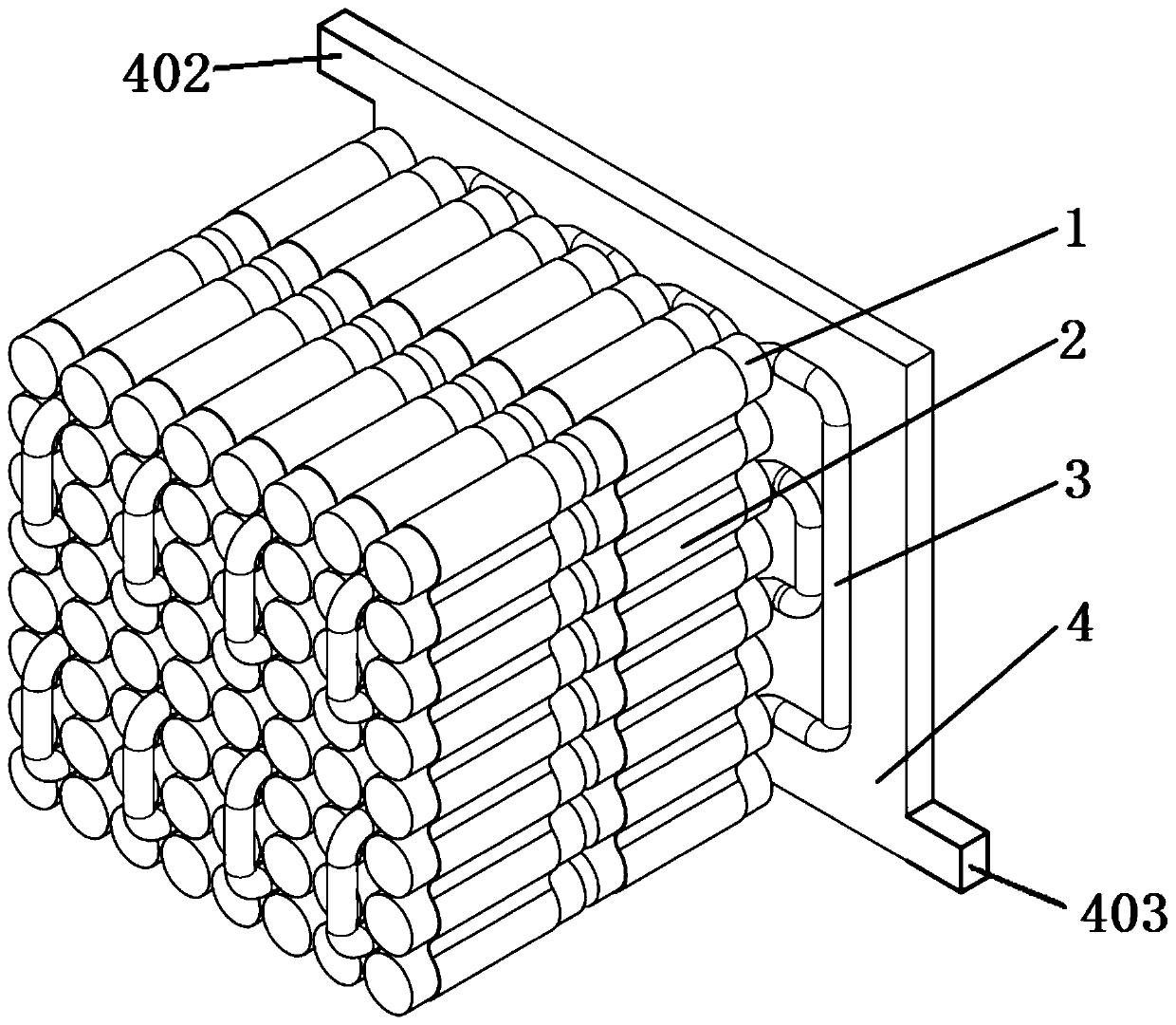
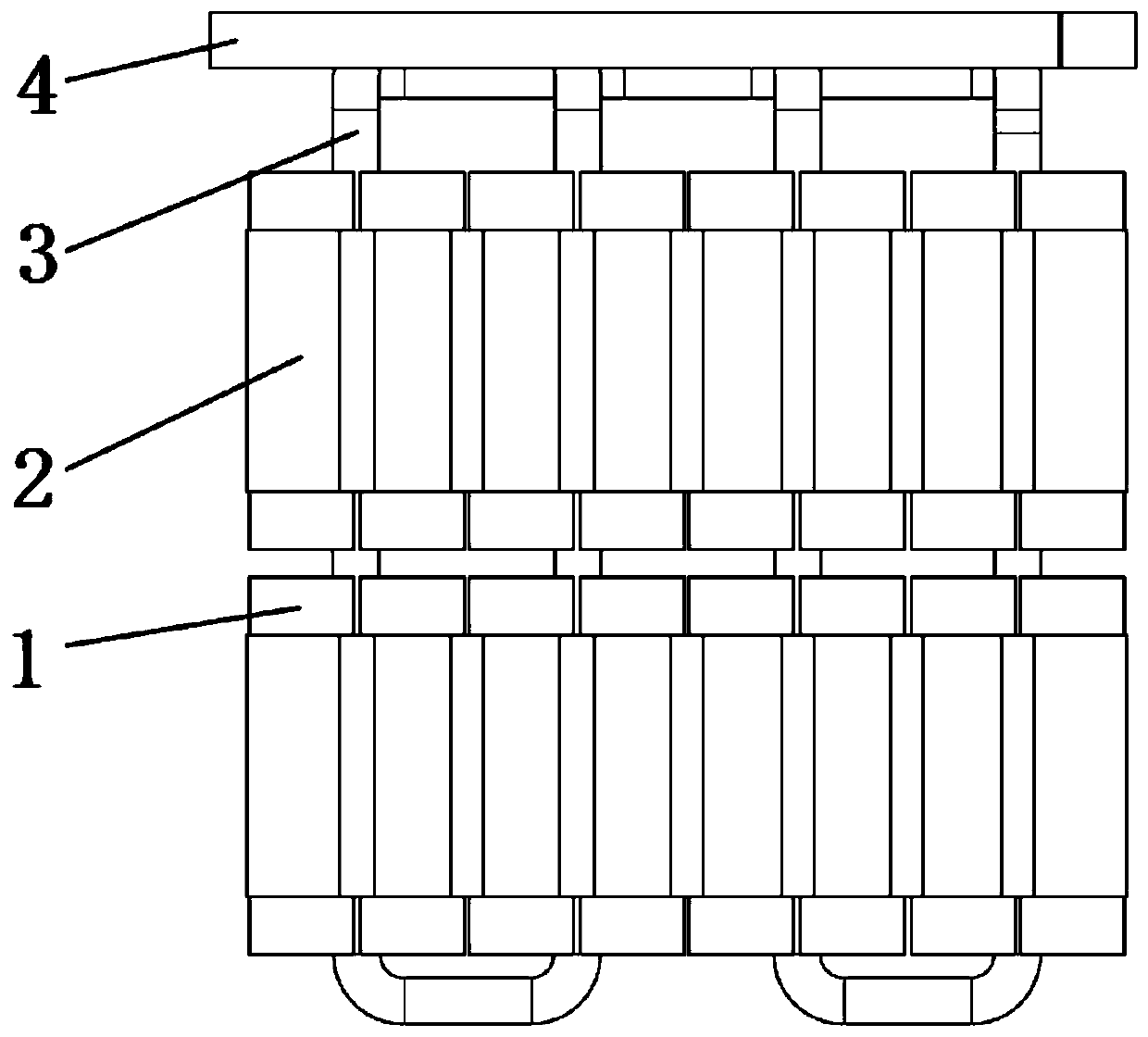
[0034] Such as Figure 1-Figure 3 A power battery liquid cooling device is shown, including a battery pack 1, a battery sleeve 2, a pulsating heat pipe 3 and a cooling channel 4 with cooling liquid inside; the battery pack 1 is arranged in the battery sleeve 2, and the pulsating heat pipe The evaporating section 301 of 3 is connected to the outer wall of the battery sleeve 2 , and the condensing section 302 of the pulsating heat pipe 3 is connected to the cooling channel 4 . The heat generated by the battery pack 1 is transferred to the cooling channel 4 through the battery sleeve 2 and the pulsating heat pipe 3 . The cooling channel 4 is only located on one side of the battery pack 1, and its design is reasonable and its structure is simple, which is beneficial to reduce energy consumption and make the structure of the liquid cooling device more compact. Among them, the pulsating heat pipe 3 is a serpentine capillary pipeline filled with working fluid inside, and the working...

Embodiment 2

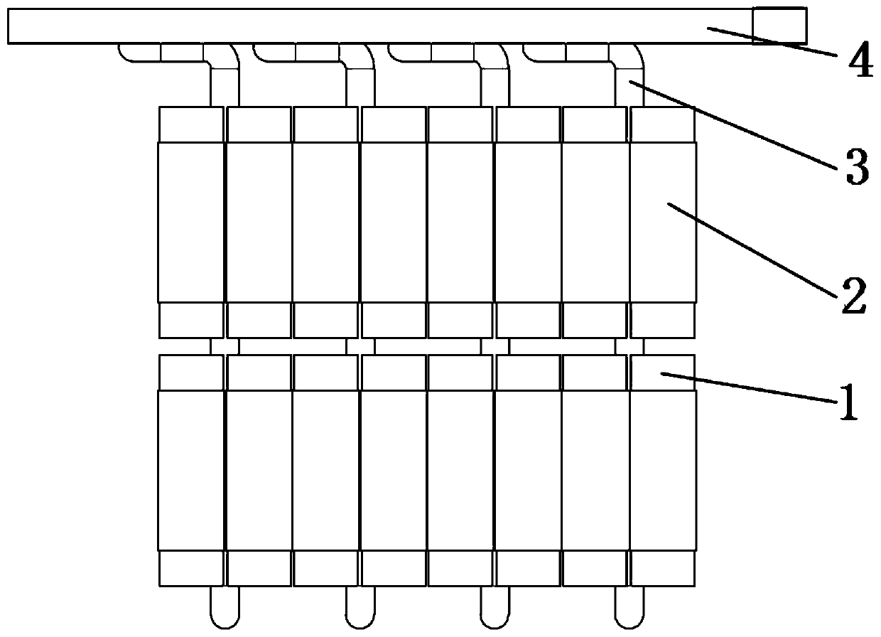
[0043] Such as Figure 10 As shown, the length of the battery sleeve 2 that is farther away from the cooling channel 4 (or the condensation section 302 of the pulsating heat pipe 3 ) wrapping the battery pack 1 increases with the distance from the cooling channel 4 . Compared with the single battery 101 closer to the cooling channel 4, the thermal resistance between the single battery 101 farther from the cooling channel 4 and the cooling channel 4 is greater. By increasing the length of the battery sleeve 2 there, Increase the contact area between the battery sleeve 2 and the single battery 101 to reduce thermal resistance; this setting can further improve the overall temperature uniformity of the battery pack 1, and set battery sleeves of different lengths for the single battery 101 in different positions Cartridge 2 for better cooling.


PUM

PropertyMeasurementUnit
angleaaaaaaaaaa

Abstract

The invention relates to the field of thermal management of power batteries, and discloses a power battery liquid cooling device. The power battery liquid cooling device comprises battery packs, battery sleeves, pulsating heat pipes and a cooling passage with coolant inside. The battery packs are respectively arranged in the battery sleeves. The evaporation section of each pulsating heat pipe is connected with the outer walls of the corresponding battery sleeves, and the condensation section of each pulsating heat pipe is connected with the cooling passage. The invention also discloses a working method of the power battery liquid cooling device. The beneficial effect is as follows: through reasonable design of the arrangement of the battery sleeves and the pulsating heat pipes, the thermalresistance of the liquid cooling device of the battery packs is reduced, the arrangement of the cooling passage on a single side of the battery packs is realized, and the temperature and temperatureuniformity of the battery packs can be well controlled.

Description

technical field [0001] The invention relates to the field of power battery thermal management, in particular to a power battery liquid cooling device and a working method thereof. Background technique [0002] Lithium-ion batteries are widely used in the electric vehicle industry because of their long cycle life, large capacity, good sustainability, high safety, low pollution, and no memory effect. The performance of lithium-ion batteries is greatly affected by temperature. Excessively high temperatures will shorten the cycle life and capacity of the battery, and even cause safety accidents in severe cases. On the one hand, the lithium-ion battery has a large specific energy and can store more energy in a limited space, but this also makes the large amount of heat released by the battery accumulate in a small space, burying the potential for thermal failure of the battery. Hidden danger. On the other hand, the heat dissipation conditions of the batteries in different posit...

Claims


Application Information

Patent Timeline
Patent Type & Authority Applications(China)
IPC IPC(8): H01M10/613H01M10/617H01M10/625H01M10/643H01M10/655H01M10/6554H01M10/6556H01M10/6568H01M10/6569H01M2/10
CPCY02E60/10
Inventor 甘云华何林峰谭梅鲜梁嘉林熊瑭
Owner SOUTH CHINA UNIV OF TECH
Why Eureka
Try Eureka