Manufacturing method for honeycomb structure

A manufacturing method and technology of honeycomb structure, applied in manufacturing tools, laser welding equipment, welding/welding/cutting items, etc., can solve the problems of complex production process, unstable quality, low efficiency, etc. Product quality, the effect of reducing labor costs

Active Publication Date: 2019-06-07
BEIJING ANDER TECH
View PDF14 Cites 4 Cited by
  • Summary
  • Abstract
  • Description
  • Claims
  • Application Information

AI Technical Summary

Problems solved by technology

[0004] The main purpose of the present invention is to provide a method for manufacturing a honeycomb structure, so as to solve the problems in the prior art that the manufacturing process of the honeycomb structure is complex, requires manual intervention, unstable quality, high cost and low efficiency

Method used


Image

  • Manufacturing method for honeycomb structure
  • Manufacturing method for honeycomb structure
  • Manufacturing method for honeycomb structure

Examples


Embodiment 1

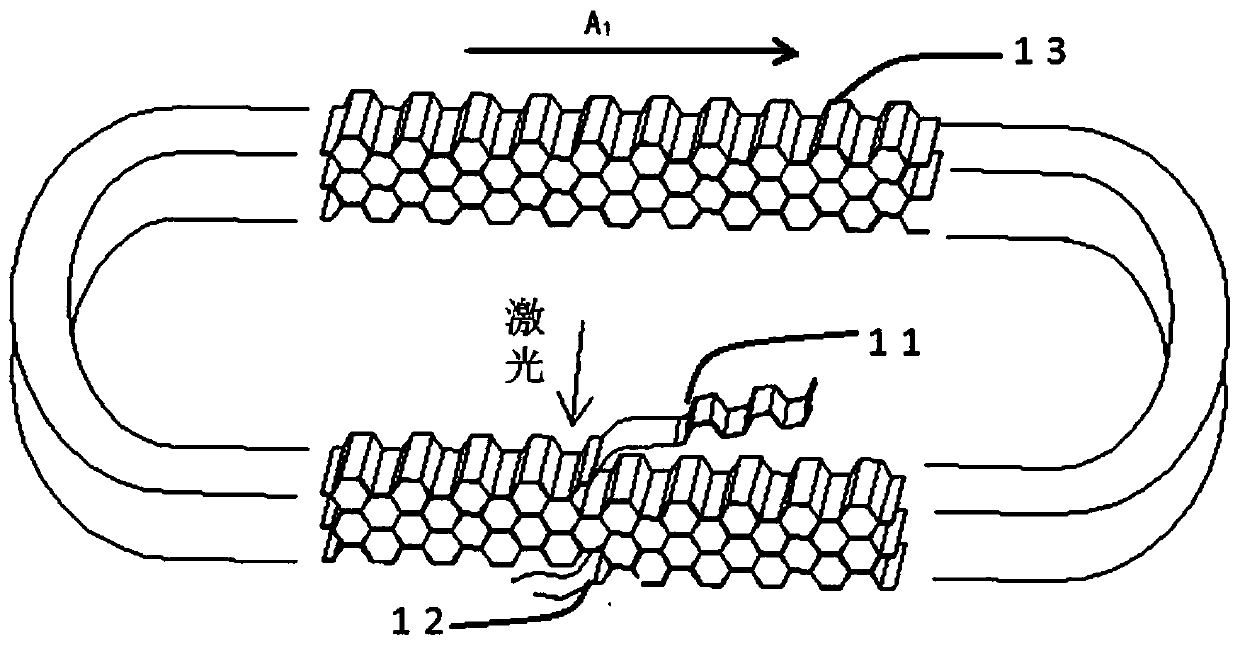
[0049] The manufacturing method of the honeycomb structure provided by the present embodiment comprises:

[0050] A continuously formed first corrugated strip is provided, the first corrugated strip has opposite first ends 11 and second ends 12, the first end 11 and the middle of the corrugated strips close to the second end 12 meet to form an annular starting honeycomb core structure, so that the initial honeycomb core structure drives the corrugated belt clockwise along the A 1 Directional circular movement, starting from the intersection of the corrugated strips, the continuous corrugated strips are driven by the initial honeycomb core structure to surround one side of the corrugated strips. The circular motion of the structure, when the continuous corrugated strips are superimposed and passed through the laser position in sequence, the convex surface of the corrugated strips are fixed by laser spot welding, and this cycle is finally processed into a first honeycomb structu...

Embodiment 2

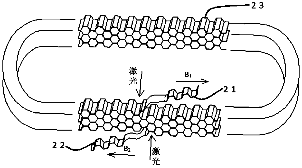
[0052] The manufacturing method of the honeycomb structure provided by the present embodiment comprises:

[0053] The second corrugated belt of continuous molding is provided, and the second corrugated belt has opposite first ends 21 and second ends 22, so that two arbitrary positions in the corrugated belt meet to form an annular initial honeycomb core structure, so that the initial honeycomb The core structure remains stationary, and with the intersection of any position as the starting point, the part between the starting point and the first end 21 in the corrugated belt starts from the starting point along the counterclockwise direction B 1 The direction of winding is superimposed on one side of the initial honeycomb core structure in sequence, and the upper laser moves synchronously with the section of corrugated belt, and at the same time makes the part between the starting point and the second end 22 of the corrugated belt move clockwise from the starting point the B 2...

Embodiment 3

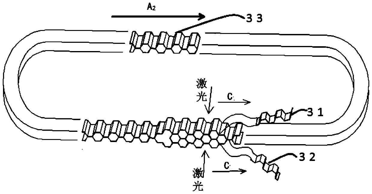
[0055] The manufacturing method of the honeycomb structure provided by the present embodiment comprises:


PUM

PropertyMeasurementUnit
thicknessaaaaaaaaaa

Abstract

The invention provides a manufacturing method for a honeycomb structure. The manufacturing method comprises the steps that a corrugated ribbon is provided, wherein the corrugated ribbon is constitutedthrough alternative connection of concave surface sections and convex surface sections, and any one of the concave surface sections and any one of the convex surface sections in the corrugated ribbonare used to form a honeycomb core grid after closed loop connection; the corrugated ribbon is annularly coiled axially with an axis as the center, so the convex surface sections and the concave surface sections can overlay to constitute a plurality of honeycomb core grids, and then the sealed loop is constituted by the honeycomb core grids; and overlaid positions between the sections of the corrugated ribbon are fixedly connected, so the honeycomb structure constituted through successive connection of the honeycomb core grids is obtained. The manufacturing method provided by the invention isdifferent from traditional honeycomb processing in that overall cutting is carried out after processing of the honeycomb structure, so a process for single sheet cutting is omitted during production,production efficiency is greatly increased and manpower cost is reduced; the cutting process and influences of cutting on belt deformation are avoided, so product quality is greatly improved; and themanufactured honeycomb cores are continuous and circulative as a whole.

Description

technical field [0001] The invention relates to the technical field of honeycomb core manufacturing, in particular to a method for manufacturing a honeycomb structure. Background technique [0002] In the prior art, the stretching method is usually used to manufacture the honeycomb structure. The stretching method refers to the use of glue to superimpose and bond the cut single-layer corrugated tapes together, and then stretch the bonded corrugated tapes to finally form Metal honeycomb core products. [0003] However, the above-mentioned traditional stacking method has obvious restrictions on the material thickness of the honeycomb core grid. Generally speaking, this method cannot be realized for materials with a thickness greater than 0.10 mm. In addition, the above-mentioned methods also have a common disadvantage, that is Both require single-piece cutting and then stacking, resulting in thin or corrugated belts that are prone to deformation or even tearing during the cut...

Claims


Application Information

Patent Timeline
Patent Type & Authority Applications(China)
IPC IPC(8): B23K26/22B23K101/02
Inventor 郑立刚潘志金
Owner BEIJING ANDER TECH
Why Eureka
Try Eureka