Supercharge Your Innovation With Domain-Expert AI Agents!

Point heat source mobile distributed seepage monitoring system and monitoring method thereof

A monitoring system, distributed technology, applied in the direction of measuring devices, permeability/surface area analysis, suspension and porous material analysis, etc., can solve the problems of adding measuring points, unable to eliminate the influence of seepage direction, and affecting monitoring accuracy, so as to avoid Ineffectiveness, meeting long-term monitoring needs, and solving the effect of spatial resolution problems

Active Publication Date: 2019-06-07
SICHUAN UNIV
View PDF4 Cites 5 Cited by
  • Summary
  • Abstract
  • Description
  • Claims
  • Application Information

AI Technical Summary

Problems solved by technology

[0007] (1) This technology uses a distributed optical fiber temperature measurement system based on Raman scattering, which has a low spatial resolution of about 1m, and the measured temperature is the average temperature within a range of 1m, with low accuracy;
[0008] (2) The heating method adopts resistance wire heating. The monitoring line of the earth-rock dam is long, and the resistance value of the resistance wire matched with the monitoring line is relatively large. To reach the predetermined heating temperature, a higher voltage and a longer heating time are often required ;
[0009] (3) The resistance value of the resistance wire will change with the change of temperature, therefore, it is difficult to ensure the stability of the heating power;
[0010] (4) There is a hidden danger of electric leakage when the cable is buried in wet soil for a long time;
[0011] (5) The heat source in the monitoring system is a linear heat source, which cannot eliminate the influence of the seepage direction on the monitoring results
This technology directly penetrates the fiber grating sensing string into the heating pipeline, and the two ends are sealed with hot melt adhesive. The position of the measuring point is fixed, but the position of the seepage is uncertain. When there is no measuring point near the seepage area , it will affect the identification accuracy of the seepage state
The monitoring range of earth-rock dams is large. To ensure spatial resolution and avoid missed judgments, it is necessary to increase the number of measuring points, thereby increasing monitoring costs.
[0016] (2) As the length of the monitoring line increases, the heating effect will weaken, thereby affecting the monitoring accuracy
[0017] (3) The heat source in the monitoring system is a linear heat source, which cannot eliminate the influence of the seepage direction on the monitoring results

Method used


Image

  • Point heat source mobile distributed seepage monitoring system and monitoring method thereof
  • Point heat source mobile distributed seepage monitoring system and monitoring method thereof
  • Point heat source mobile distributed seepage monitoring system and monitoring method thereof

Examples


Embodiment 1

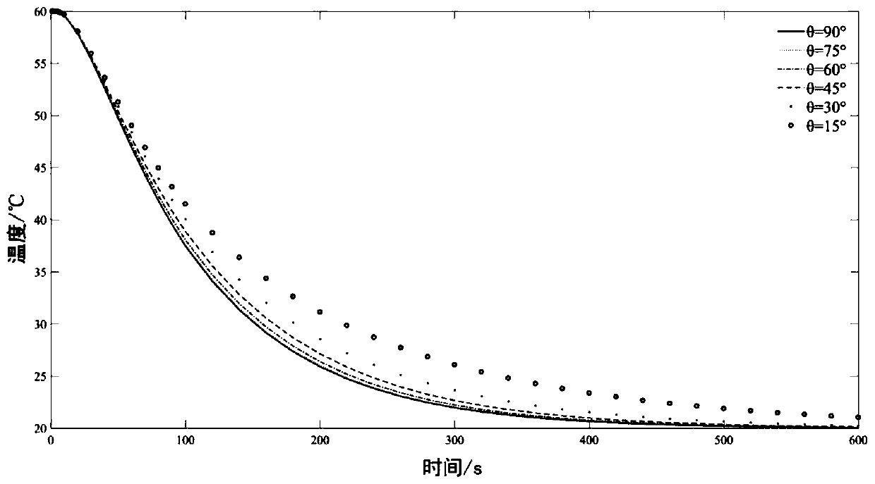
[0063] In order to verify the effectiveness of the point heat source seepage monitoring system developed by the present invention, a Figure 9The test model shown (H1=100mm, H2=600mm, H3=600mm, B=300mm, L=800mm), under the influence of dual factors of seepage velocity and seepage direction, the calibration test was carried out. The shell of the model box is spliced ​​by 3mm thick steel plates, and a square steel pipe frame is set outside the box as a lateral support. There are 4 drain pipes at the bottom of the box, and valves are installed on the drain pipes to control the flow. Embed 4 monitoring pipes 7 (PE-RT pipes, outer diameter 20mm, wall thickness 2mm) in the box, the axis and the infiltration direction (from top to bottom) are respectively 90°, 70°, 50°, 30° °. First, lay 10cm-thick gravel at the bottom of the box as a reverse filter layer, and then fill in river sand to the design elevation. Before filling the river sand, put a steel bar in the monitoring pipe 7 i...

Embodiment 2

[0069] On the basis of Example 1, using Figure 8 In the improved scheme shown, pure water is poured into the monitoring pipe 7 to carry out calibration tests at different seepage velocities. Each working condition ln(λ-λ θ ) vs. time curve, see Figure 11 . It can be seen that as the seepage velocity increases, the temperature drops faster, and ln(λ-λ θ ) has a strong correlation with the seepage velocity. According to ln(λ-λ θ ) time history curve, and divide it into three stages: rapid cooling period (0-200s), transitional period (200s-300s), and slow cooling period (300s-temperature stable). In the fast cooling section and the slow cooling section, ln(λ-λ θ ) time history curve is approximately linear, using the data from 50s to 200s and 300s to 600s respectively to fit ln(λ-λ θ ) The slope ξ of the time history curve in these two periods v1 and ξ v2 , as shown in Table 2. ξ v1 and ξ v2 The absolute values ​​of both increase with the increase of the seepage vel...


PUM


Abstract

The invention discloses a point heat source mobile distributed seepage monitoring system and a monitoring method thereof. The monitoring system comprises a sensing heating element, a monitoring tube,a voltage-stabilized source, a fiber grating demodulator, a notebook computer, an armored cable and a wire. Sensing elements in the sensing heating element are connected in series by the armored cable; the armored cable is connected with the fiber grating demodulator; and multi-measuring-point synchronous measurement is carried out by using a wavelength division multiplexing technology. The fibergrating demodulator is connected with the notebook computer. The sensing elements in the sensing heating element are connected in series by the wire; and the two ends of the wire are connected with the voltage-stabilized source to form a closed loop for electrification and heating. The sensing heating element penetrates the monitoring tube. The point heat source mobile distributed seepage monitoring system has the advantages: with construction of the point heat source heating system, the influence on the seepage monitoring result by the seepage direction can be eliminated; a spatial resolutionproblem of the fiber grating quasi-distributed sensing system is solved by mobile distributed monitoring; and the monitoring line can be taken out from the monitoring tube to carry out repairing or replacement.

Description

technical field [0001] The invention relates to the technical field of geotechnical engineering seepage monitoring, in particular to an optical fiber grating point heat source moving distributed seepage monitoring system and a monitoring method thereof. Background technique [0002] Seepage problems exist in many geotechnical projects. Seepage will affect the stability of rock and soil mass and directly threaten the safety of the project. The well-known failure of the Teton Dam in the United States was caused by seepage damage. [1] . Seepage is concealed, random in space and time, and most of the prevention and control of seepage needs to be supplemented by certain monitoring methods. Therefore, seepage monitoring is an important monitoring content in the field of geotechnical engineering. [0003] Seepage monitoring methods are diverse, including: (1) Conventional monitoring methods. This type of method has a long history, with many engineering applications and experience...

Claims


Application Information

Patent Timeline
IPC IPC(8): G01N15/08
Inventor 陈江方晓熊峰
Owner SICHUAN UNIV
Features
  • R&D
  • Intellectual Property
  • Life Sciences
  • Materials
  • Tech Scout
  • Unparalleled Data Quality
  • Higher Quality Content
  • 60% Fewer Hallucinations
Learn More