Supercharge Your Innovation With Domain-Expert AI Agents!

Processing technology of distribution pipe and engine high pressure oil rail assembly comprising same

A processing technology and distribution pipe technology, applied in the direction of engine components, machines/engines, mechanical equipment, etc., can solve the problems of high energy consumption in the process, high resource waste rate, and low recycling rate of waste materials

Inactive Publication Date: 2019-06-11
SHANGHAI WINKELMANN LONGCHUAN (SWL) MOTORCOMPONENTS CO LTD
View PDF13 Cites 4 Cited by
  • Summary
  • Abstract
  • Description
  • Claims
  • Application Information

AI Technical Summary

Problems solved by technology

[0005] The object of the present invention is to provide a processing technology for distribution pipes and an engine high-pressure oil rail assembly containing the distribution pipes, mainly to solve the problems of complicated manufacturing process, high energy consumption, poor economy and waste recycling in the above-mentioned prior art. The utilization rate is not high, the resource waste rate is high, and chemical cleaning is required at the same time, and the environmental pollution is high. The manufacturing process of the distribution pipe processing technology of the present invention is simple, mature, easy to promote, extremely economical, and the structure of the inner cavity is flexible. It can meet the different needs of users, has a high rate of waste recycling, saves resources, and has no chemical pollution, which can play a positive role in environmental protection.
[0006] The distribution pipe of the present invention can also solve the problem of a single inner cavity structure in the prior art, and can be processed into various inner cavities with different structures through the processing technology of the present invention, so as to meet the requirements of different engine high-pressure fuel rail assemblies for distribution pipes

Method used


Image

  • Processing technology of distribution pipe and engine high pressure oil rail assembly comprising same
  • Processing technology of distribution pipe and engine high pressure oil rail assembly comprising same
  • Processing technology of distribution pipe and engine high pressure oil rail assembly comprising same

Examples


Embodiment Construction

[0130] The present invention will be further described below in combination with specific embodiments. It should be understood that these examples are only used to illustrate the present invention and are not intended to limit the scope of the present invention. In addition, it should be understood that after reading the teachings of the present invention, those skilled in the art can make various changes or modifications to the present invention, and these equivalent forms also fall within the scope defined by the appended claims of the present application.

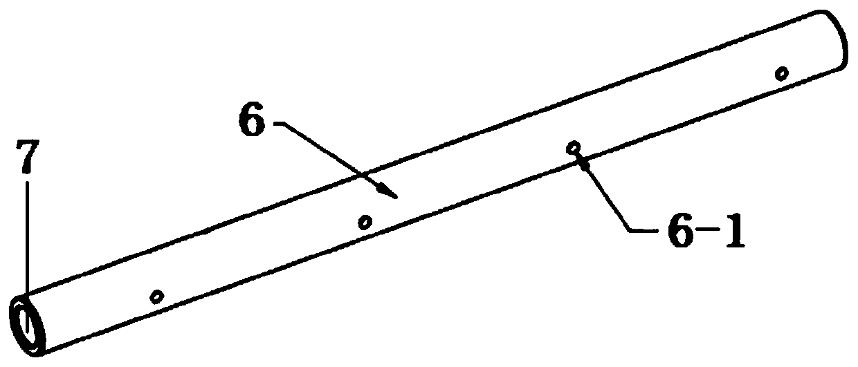
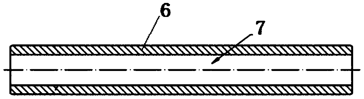
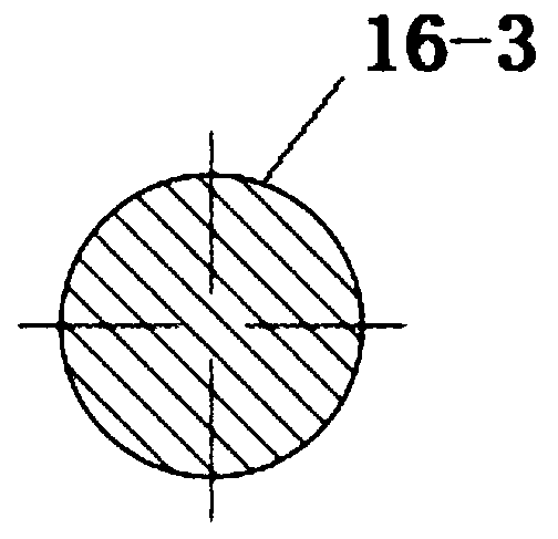
[0131] see Figure 1 to Figure 4 , Embodiment 1, a distribution pipe provided by the present invention includes a distribution pipe body 6, an inner chamber 7 is provided in the distribution pipe body 6, and both ends of the inner chamber 7 are opened to form a through-hole inner chamber 7, which is characterized in that: The cross-sectional shape of the inner cavity is circular, square, rectangular, elliptical, trapezo...


PUM

PropertyMeasurementUnit
Depthaaaaaaaaaa

Abstract

The invention provides a processing technology of a distribution pipe and an engine high pressure oil rail assembly comprising the distribution pipe; the distribution pipe comprises a distribution pipe body; an inner cavity is arranged in the distribution pipe body; the two ends of the inner cavity are opened to form a through-hole type inner cavity. According to the invention, the problems that the distribution pipe has complicated manufacturing process, high process energy consumption, poor economy, low waste recycling rate, high resource waste rate, chemical cleaning and high environmentalpollution degree in the prior art are solved; and the processing technology of the distribution pipe provided by the invention is simple, mature, easy to promote, economical, and flexible in structure, so the processing technology can meet different needs of users; with high waste recycling rate, resource saving, and no chemical pollution, the processing technology plays a positive role to environment protection.

Description

technical field [0001] The invention relates to a component of an engine, in particular to a distribution pipe and its processing technology, and an engine high-pressure oil rail assembly. Background technique [0002] The role of the fuel rail: Take the gasoline engine as an example. The gasoline engine has multiple cylinders, and each cylinder is independently equipped with a fuel injector to provide gasoline. All the fuel injectors are connected to a common oil pipe (referred to as fuel common rail) ). The working principle is that the gasoline is delivered from the fuel tank to the oil rail by the oil pump at a certain pressure, and there is a constant working pressure inside the oil rail to send the gasoline to each injector, and the injector injects the gasoline as required through the electronic control device. into the cylinder for combustion. The fuel rail is independent from the gasoline engine and remains constant throughout the injection combustion process. ...

Claims


Application Information

Patent Timeline
IPC IPC(8): B23P15/00F02M55/00F02M55/02F02M61/14
CPCB23P15/00F02M55/004F02M55/02F02M55/025F02M61/14
Inventor 肖松黄陆鑫康慧忠程水良亨宁·哈特曼杨卫国
Owner SHANGHAI WINKELMANN LONGCHUAN (SWL) MOTORCOMPONENTS CO LTD
Features
  • R&D
  • Intellectual Property
  • Life Sciences
  • Materials
  • Tech Scout
  • Unparalleled Data Quality
  • Higher Quality Content
  • 60% Fewer Hallucinations
Learn More