Scouring-resistant slurry valve

An erosion-resistant and slurry technology, which is applied in the field of erosion-resistant slurry valves, can solve problems such as short service life, easy to be eroded, valve stuck, etc., to improve physical and chemical properties, prolong service life, and improve valve body life Effect

Pending Publication Date: 2019-06-11
GUANGXI KEDE VALVE CO LTD
View PDF3 Cites 1 Cited by
  • Summary
  • Abstract
  • Description
  • Claims
  • Application Information

AI Technical Summary

Problems solved by technology

[0008] According to the research of the present inventors, at present, all high-pressure slurry valves in China generally adopt Y-type globe valves, but because the structure adopts Y-type, it is easy to generate eddy currents and damage the valves. The valve plate is located in the center of the valve cavity, and is easily affected For flushing, the valve stem adopts the screw nut, which makes it difficult to seal and is exposed outside, which is easy to cause jamming and wear. The valve is integrally cast, and the material at the flushing position is difficult to replace. It needs to be replaced completely, and the cost is too high, so it is used as a whole. The service life is short; there are also some hard-sealed ball valve structures, but due to the sliding seal, the valve cavity cannot be cleaned, and the valve is stuck after the material settles. Not long; some users use hemispherical valves. Due to the structural problems of the channel and valve plate, the service life is also very short; the best Y-type slurry valve currently used has a service life of only 45 days in a special environment, which affects production safety and order. Therefore, the high pressure, high temperature and high corrosion resistance slurry valve has become a difficult problem in the industry

Method used


Image

  • Scouring-resistant slurry valve
  • Scouring-resistant slurry valve

Examples


Embodiment 1

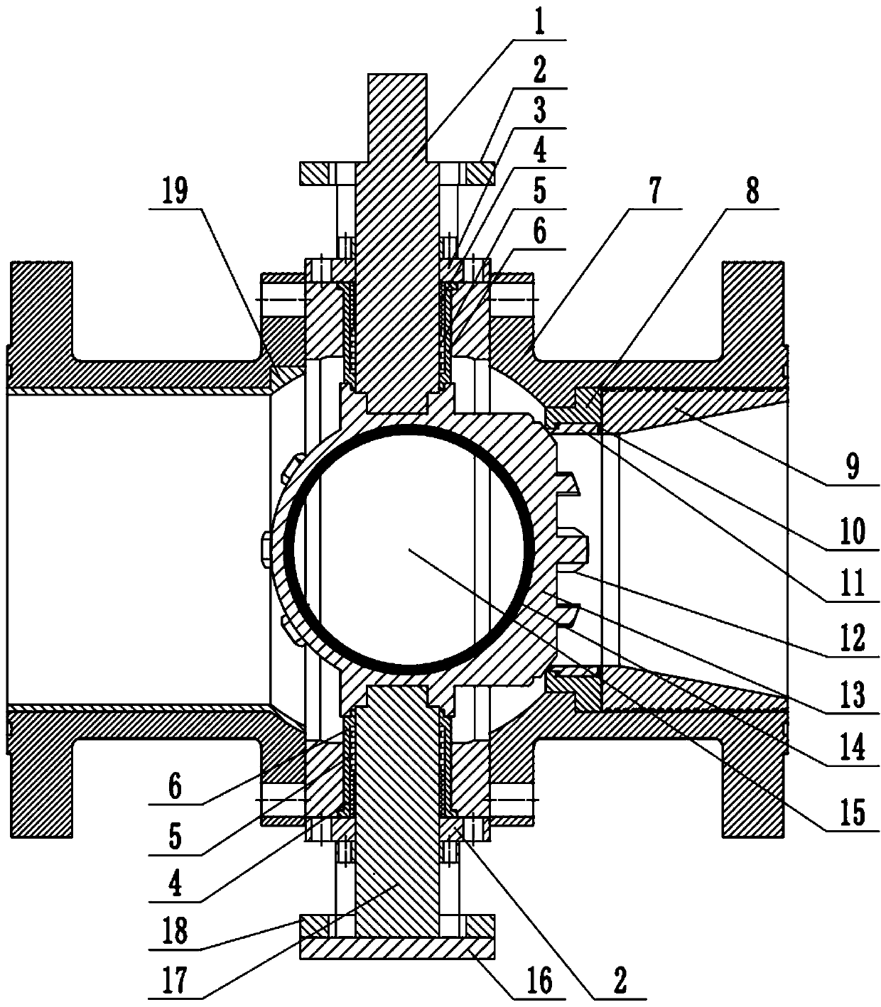
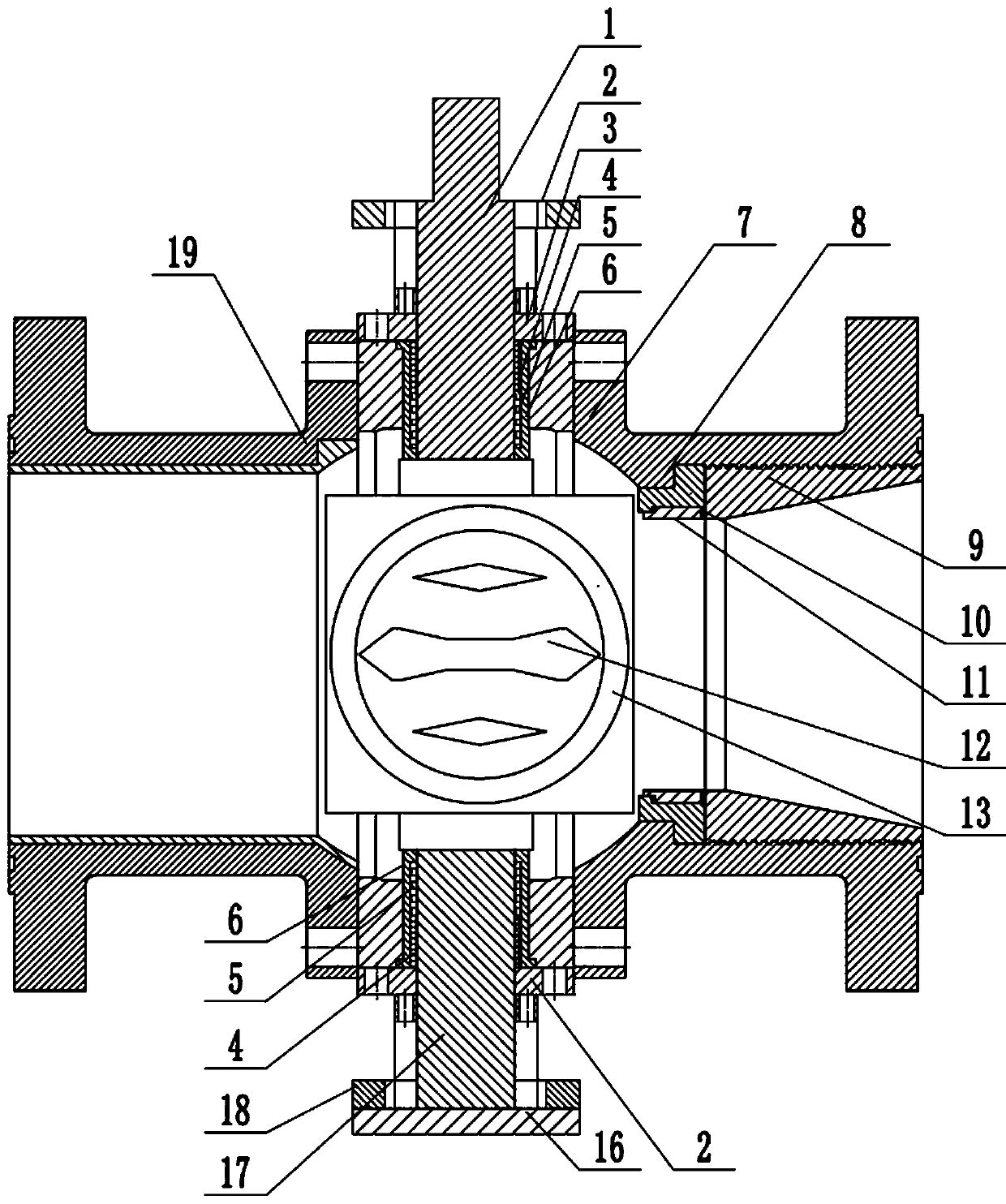
[0037] An erosion-resistant slurry valve, comprising an upper valve shaft 1, a large gland 6, a valve body 7, a valve plate 13 and a lower valve shaft 17, and the side of the valve body 7 is provided with an inlet and an outlet; The top surface and the bottom surface of the valve body 7 are respectively provided with mounting holes for the large gland 6, the large gland 6 is installed in the mounting hole, the valve plate 13 is supported and fixed in the valve body 7 by the large gland 6, and the upper The valve shaft 1 and the lower valve shaft 17 respectively pass through the large gland 6 installed on the top surface and the bottom surface of the valve body 7 and then connect with the valve plate 13. The coupling hole of the valve shaft is not subject to any impact, and is firm and reliable; packing 5 and bearing sleeve 4 are installed between the large gland 6 and the valve shaft, and the packing gland 3 presses the packing 5 and the bearing sleeve 4 supporting the rotation...

Embodiment 2

[0041] An erosion-resistant slurry valve, comprising an upper valve shaft 1, a large gland 6, a valve body 7, a valve plate 13 and a lower valve shaft 17, and the side of the valve body 7 is provided with an inlet and an outlet; The top surface and the bottom surface of the valve body 7 are respectively provided with mounting holes for the large gland 6, the large gland 6 is installed in the mounting hole, the valve plate 13 is supported and fixed in the valve body 7 by the large gland 6, and the upper The valve shaft 1 and the lower valve shaft 17 respectively pass through the large gland 6 installed on the top surface and the bottom surface of the valve body 7 and then connect with the valve plate 13. The coupling hole of the valve shaft is not subject to any impact, and is firm and reliable; packing 5 and bearing sleeve 4 are installed between the large gland 6 and the valve shaft, and the packing gland 3 presses the packing 5 and the bearing sleeve 4 supporting the rotation...

Embodiment 3

[0047] An erosion-resistant slurry valve, comprising an upper valve shaft 1, a large gland 6, a valve body 7, a valve plate 13 and a lower valve shaft 17, and the side of the valve body 7 is provided with an inlet and an outlet; The top surface and the bottom surface of the valve body 7 are respectively provided with mounting holes for the large gland 6, the large gland 6 is installed in the mounting hole, the valve plate 13 is supported and fixed in the valve body 7 by the large gland 6, and the upper The valve shaft 1 and the lower valve shaft 17 respectively pass through the large gland 6 installed on the top surface and the bottom surface of the valve body 7 and then connect with the valve plate 13. The coupling hole of the valve shaft is not subject to any impact, and is firm and reliable; packing 5 and bearing sleeve 4 are installed between the large gland 6 and the valve shaft, and the packing gland 3 presses the packing 5 and the bearing sleeve 4 supporting the rotation...


PUM


Abstract

Provided is a scouring-resistant slurry valve. The scouring-resistant slurry valve comprises an upper valve shaft, large pressing covers, a valve body, a valve plate and a lower valve shaft. A flow inlet and a flow outlet are formed in the side face of the valve body; mounting holes for the large pressing covers are formed in the top face and the bottom face of the valve body correspondingly, thelarge pressing covers are mounted in the mounting holes, the valve plate is supported and fixed in the valve body through the large pressing covers, and the upper valve shaft and the lower valve shaftpenetrate through the large pressing covers and then are connected with the valve plate; packing and a bearing sleeve are mounted between each large pressing cover and the corresponding valve shaft,and the packing and the bearing sleeves supporting the valve shafts to rotate are pressed in the large pressing covers through glands; an upper support is mounted on the top face of the valve body; alower support is mounted at the bottom of the valve body; a bottom cover for limiting the lower valve shaft is mounted on the lower support; the valve plate is provided with a circular-hole valve plate channel for passing of slurry; a valve seat is arranged on the flow inlet of the side face of the valve body, and the valve seat is fixed and limited in the flow inlet through a nut; the diameter ofthe valve plate channel is smaller than that of an alloy sleeve and larger than the diameter of the valve seat. The slurry valve is good in airtightness, resistant to high-pressure scouring and longin service life.

Description

technical field [0001] The invention relates to the technical field of valves, in particular to an erosion-resistant slurry valve. technical background [0002] A valve is a control component in a fluid delivery system, with functions such as cut-off, regulation, flow diversion, reverse flow prevention, pressure stabilization, flow diversion, or overflow pressure relief. Valves used in fluid control systems range from the simplest cut-off valves to various valves used in extremely complex automatic control systems, with a wide variety of varieties and specifications. Valves can be used to control the flow of various types of fluids such as air, water, steam, various corrosive media, mud, oil, liquid metal and radioactive media. Valves are also divided into cast iron valves, cast steel valves, stainless steel valves (201, 304, 316, etc.), chrome-molybdenum steel valves, chrome-molybdenum-vanadium steel valves, duplex steel valves, plastic valves, non-standard custom-made val...

Claims


Application Information

Patent Timeline
Patent Type & Authority Applications(China)
IPC IPC(8): F16K5/06F16K5/08F16K5/20F16K27/06F16K47/02
Inventor 刘向阳
Owner GUANGXI KEDE VALVE CO LTD
Why Eureka
Try Eureka