Detection system, method, device and computer-readable storage medium
A detection system and computer technology, applied in computing, image analysis, instruments, etc., to achieve the effect of simplifying test steps, simplifying detection difficulty, and improving detection accuracy
- Summary
- Abstract
- Description
- Claims
- Application Information
AI Technical Summary
Problems solved by technology
Method used
Image
Examples
Embodiment 1
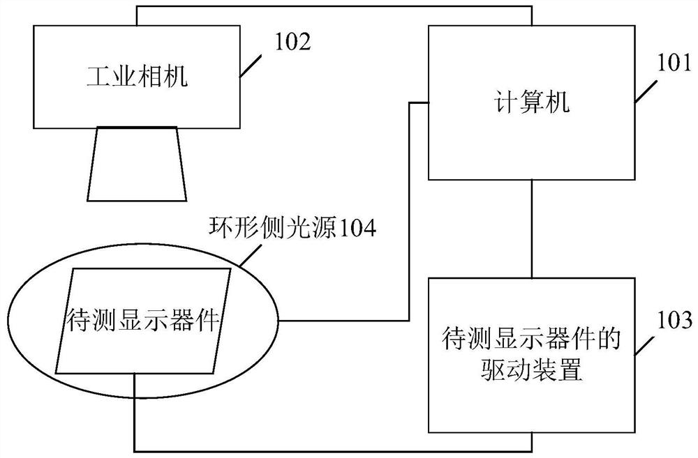
[0038] Embodiment 1 of the present application provides a detection system, and the structural diagram of the detection system is as follows: figure 1 As shown, the detection system includes: a computer 101, an industrial camera 102 and a drive device 103 for the display device to be tested.
[0039] Both the industrial camera 102 and the driving device 103 of the display device to be tested are electrically connected to the computer 101;
[0040] The computer 101 is used to control the driving device 103 of the display device under test to drive the display device under test to display the target image; the computer 101 controls the industrial camera 102 to obtain the target image displayed by the display device under test; the computer 101 performs image reconstruction on the target image according to the conversion model. Sampling and transformation to obtain the target image after image registration; computer 101 performs brightness mapping on the target image after image ...
Embodiment 2
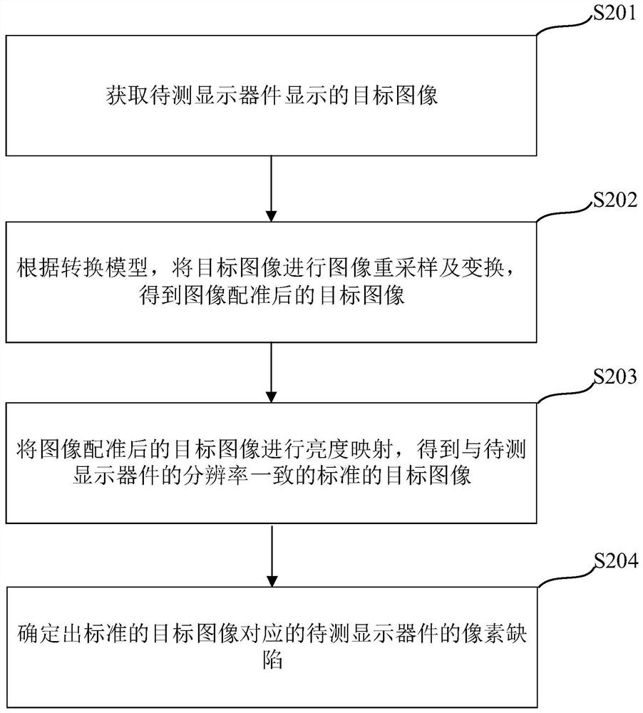
[0047] A kind of detection method is provided in the embodiment of the present application, the schematic flow chart of this method is as follows figure 2 As shown, the method includes:
[0048] S201. Acquire a target image displayed by a display device under test.
[0049] It should be noted that the computer acquires the target image displayed by the display device under test.
[0050] S202. Perform image resampling and transformation on the target image according to the conversion model to obtain a target image after image registration.
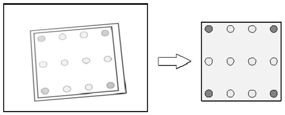
[0051] It should be noted that, according to the conversion model, the computer performs image resampling and transformation on the target image to obtain the target image after image registration. image 3 A schematic diagram of the effect of image registration is provided, such as image 3 As shown, after the target image captured by the industrial camera is registered, the target image after image registration is obtained.
[0052]...
Embodiment 3
[0076] Based on the same inventive concept, the embodiment of the present application also provides a detection device, the structural diagram of which is shown in Figure 6 As shown, the detection device 60 includes an acquisition module 601 , a first processing module 602 , a second processing module 603 and a third processing module 604 .
[0077] An acquisition module 601, configured to acquire a target image displayed by the display device under test;
[0078] The first processing module 602 is used to perform image resampling and transformation on the target image according to the conversion model, so as to obtain the target image after image registration;
[0079] The second processing module 603 is configured to perform brightness mapping on the target image after image registration to obtain a standard target image consistent with the resolution of the display device to be tested;
[0080] The third processing module 604 is configured to determine the pixel defect of...
PUM
 Abstract
Description
Claims
Application Information
 - R&D
- Intellectual Property
- Life Sciences
- Materials
- Tech Scout
- Unparalleled Data Quality
- Higher Quality Content
- 60% Fewer Hallucinations
Browse by: Latest US Patents, China's latest patents, Technical Efficacy Thesaurus, Application Domain, Technology Topic, Popular Technical Reports.
© 2025 PatSnap. All rights reserved.Legal|Privacy policy|Modern Slavery Act Transparency Statement|Sitemap|About US| Contact US: help@patsnap.com


