Low temperature resistant high speed permanent magnet motor high strength rotor structure

A permanent magnet motor, rotor structure technology, applied in the magnetic circuit shape/style/structure, magnetic circuit rotating parts and other directions, can solve the problems of poor rotor heat dissipation, easy breakage, poor mechanical strength and so on

Inactive Publication Date: 2019-06-11
HARBIN UNIV OF SCI & TECH
View PDF5 Cites 2 Cited by
  • Summary
  • Abstract
  • Description
  • Claims
  • Application Information

AI Technical Summary

Problems solved by technology

[0004] The purpose of the present invention is to provide a high-strength rotor structure for low-temperature resistant high-speed permanent magnet motors, so as to solve the shortcomings of e

Method used


Image

  • Low temperature resistant high speed permanent magnet motor high strength rotor structure
  • Low temperature resistant high speed permanent magnet motor high strength rotor structure
  • Low temperature resistant high speed permanent magnet motor high strength rotor structure

Examples


Embodiment Construction

[0018] In order to make the technical means, creative features, goals and effects achieved by the present invention easy to understand, the invention will be further elaborated below in conjunction with specific embodiments.

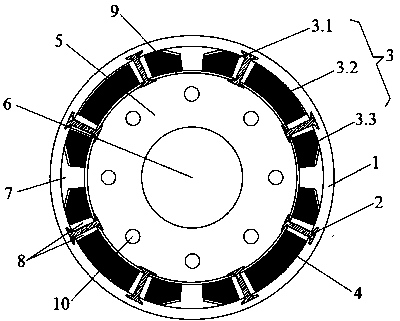
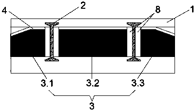
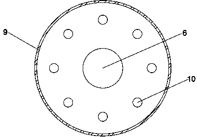
[0019] see Figure 1 to Figure 4 , High-strength rotor structure of low-temperature resistant high-speed permanent magnet motor, including rotor core 5, permanent magnet pole 3, rib 2, rotating shaft 6, and cooling holes 10.

[0020] The outer side of the rotor core 5 is fixed with permanent magnet poles 3 equidistantly arranged along the circumferential direction, the rotor core 5 is connected with the permanent magnet poles 3 through an anaerobic adhesive layer 9, and the outer side of the permanent magnet poles 3 is pasted with a copper plating layer 4 .

[0021] A first cooling branch 7 is provided between the permanent magnet poles 3, and each of the permanent magnet poles 3 is unevenly divided into No. 1 permanent magnet 3.1, No. 2 permanent magne...


PUM


Abstract

The invention provides a low temperature resistant high speed permanent magnet motor high strength rotor structure and belongs to the technical field of a motor structure. The rotor structure comprises a rotor core, permanent magnet poles, reinforcing ribs, a rotation shaft and heat dissipation holes. The permanent magnet poles which are equidistantly arranged along a peripheral direction are fixed at an outer side of the rotor core. The rotor core is connected with the permanent magnet poles through utilization of anaerobic adhesive layers. A copper plated layer is adhered at an outer side ofthe permanent magnet poles. A first heat dissipation branch is set between the adjacent permanent magnet poles. Each permanent magnet pole is dividedly into No.1 permanent magnet, No.2 permanent magnet and No.3 permanent magnet nonuniformly. Two ends of the reinforcing ribs are inlaid at the outer side of the rotor iron and an inner side of a carbon fiber sheath. The reinforcing ribs, the rotor core, the carbon fiber sheath and the permanent magnet poles form a second heat dissipation branch. The rotor structure has relatively high practicability. On the premise of ensuring rotation speed ofa high speed permanent magnet motor, cogging torque of a rotor is reduced, mechanical performance of the motor rotor in a low temperature environment is improved, and heat dissipation capability in the rotor is improved.

Description

technical field [0001] The invention relates to the technical field of motor and electric appliance transmission, in particular to a high-strength rotor structure of a low-temperature resistant high-speed permanent magnet motor. Background technique [0002] The main component of liquefied natural gas (LNG) is methane. LNG has the advantages of being odorless, colorless, non-toxic and non-corrosive. With the widespread use of LNG, the safe transportation of LNG has become an important link in the natural gas industry chain. When the transportation volume of LNG is large, LNG pumps are often used for transportation . As the core component of the LNG pump, the cryogenic motor is immersed in the -161°C cryogenic LNG together with the LNG pump to provide power for the normal operation of the cryopump. LNG has a low temperature of -161°C and is flammable. Therefore, the low temperature motor material for submersible LNG pumps must not only withstand the low temperature of -161°...

Claims


Application Information

Patent Timeline
IPC IPC(8): H02K1/27H02K1/28H02K1/32
Inventor 戈宝军温亚垒王立坤张永生
Owner HARBIN UNIV OF SCI & TECH
Why Eureka
Try Eureka