
A kind of downhole survey method and equipment

A detection hole and detection device technology, which is applied in the field of geological exploration, can solve the problems of construction influence, failure to confirm the attributes of obstacles, high-temperature heat pipes, etc., and achieve the effect of increasing the detection range and angle

Active Publication Date: 2022-07-26
广东有色工程勘察设计院
View PDF6 Cites 0 Cited by
  • Summary
  • Abstract
  • Description
  • Claims
  • Application Information

AI Technical Summary

Problems solved by technology

The current problem is that the drawings of the pipeline ownership unit and the actual pipeline location on the site cannot be all one-to-one correspondence. It is hard to find one, and the excavation depth can reach 3m is the limit
But urban construction requires geological survey, geological survey requires drilling, and the fact that drilling can only start from the ground cannot be changed
[0004] Due to historical and management reasons, many pipelines have brought great adverse effects to the current urban construction, especially in the preliminary survey stage of construction, the damage of existing pipelines will not only cause difficulties for people's life and production, and some even cause Secondary accidents, such as gas pipes, high-voltage electricity, high-temperature heat pipes, etc., or even disasters
[0005] All existing detection equipment can only perform indirect detection, and the confirmation of the attributes of obstacles (target objects) can only be indirect speculation, and cannot be accurately confirmed
Sometimes there is indeed no pipeline under the drilling point, and various obstacles will still be encountered during drilling. Drilling is abandoned because the attributes of obstacles cannot be confirmed, which has a serious impact on the design and construction of engineering construction.
In addition, during the drilling process, there will be sediment, sludge, sewage, etc. in the well. Some existing detection equipment with imaging observation functions such as cameras cannot observe the surface of obstacles through the sludge and sewage, thereby increasing It is more difficult to judge obstacles, and sometimes it is impossible to confirm obstacles, which affects construction efficiency

Method used


Image

  • A kind of downhole survey method and equipment
  • A kind of downhole survey method and equipment
  • A kind of downhole survey method and equipment

Examples


Embodiment 1

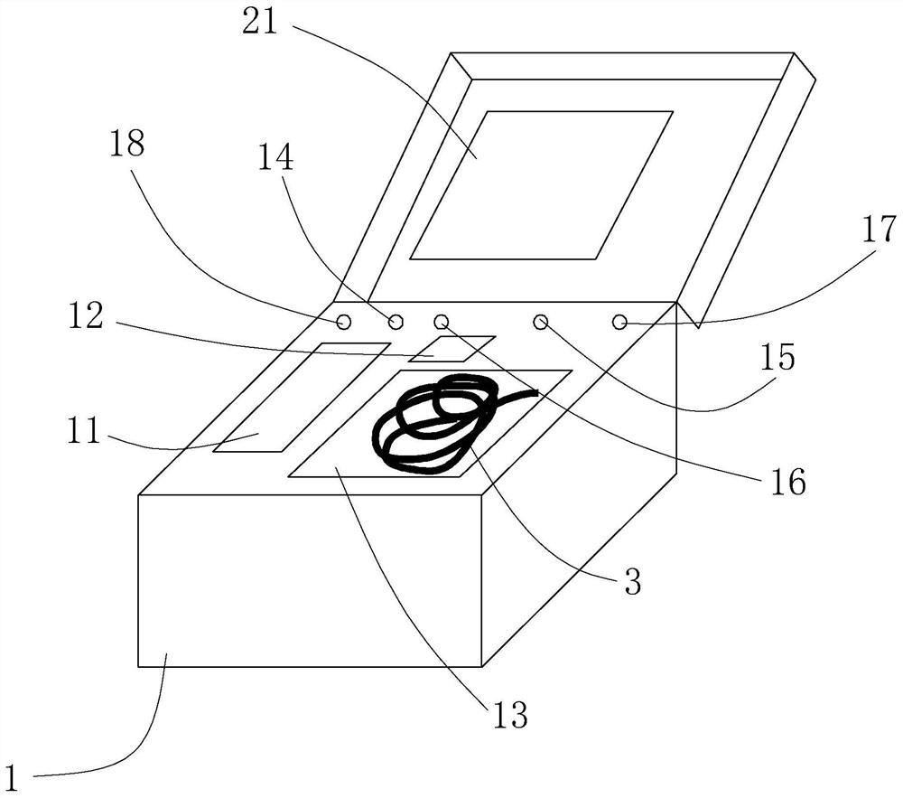
[0047] A borehole observation tester, such as Figure 1 to Figure 2 As shown, it includes a carrier box 1, on which a display 21 and a water supply device are installed. The water supply device is used to pump transparent liquids such as water, etc. The water supply device can be various types of water pumps, including submersible pumps, centrifugal pumps, diaphragms Pumps, etc., the cargo box 1 is provided with a water tank 11 that communicates with the water supply device. The water supply device can also communicate with the direct water supply interface 18 provided on the cargo box 1. The cargo box 1 is also fixed with a battery box 12. The battery box 12 is used to disassemble and place the battery, and the battery can be used for portable power supply to the water supply device in construction occasions without power supply conditions. The cargo box 1 is also provided with a storage slot 13, and the storage slot 13 is used for placing the water pipe 3 and other pipelines...

Embodiment 2

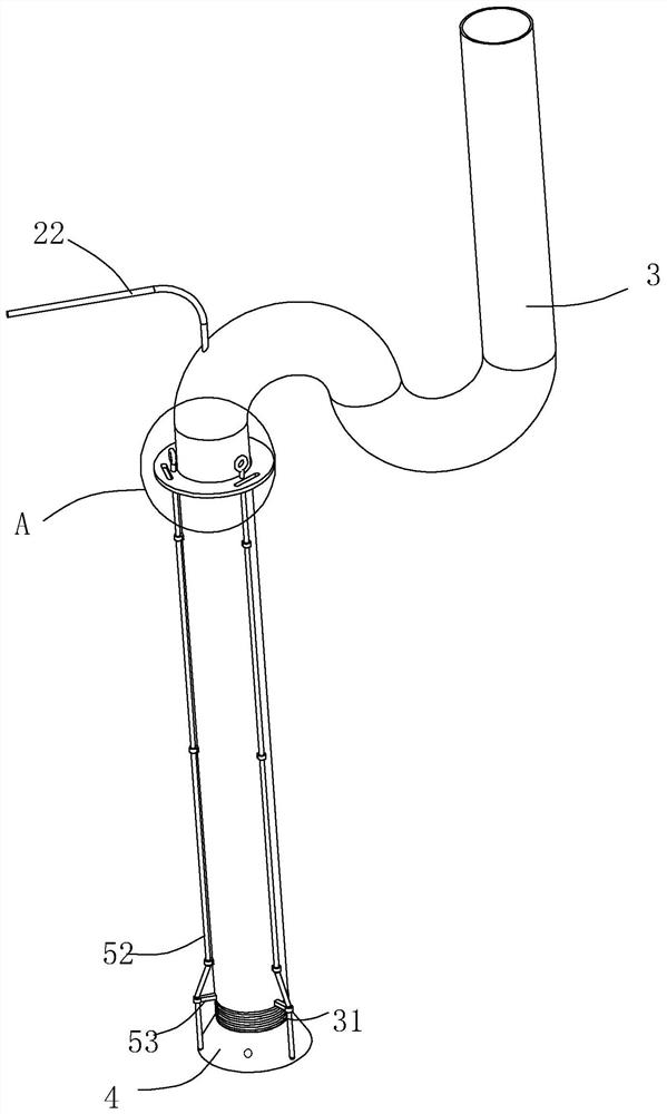
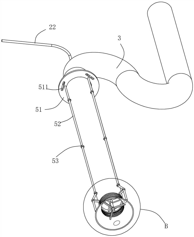
[0062] The difference between this embodiment and Embodiment 1 is that the detection device 2 is wirelessly connected to the display 21 , and during the wireless connection, data transmission can be performed by means of Bluetooth, WIFI, or the like. It also includes a wireless steering control system. The wireless steering control system includes a flexible section communicating with the water outlet of the water delivery pipe 3, a protective cover 4 communicating with the end of the flexible section away from the water delivery pipe 3, and a wireless control assembly. The flexible section adopts a bellows 31. The wireless control assembly includes a relatively moving chassis 61 and a turntable 62. Both the chassis 61 and the turntable 62 are annular, and clean water is circulated in the middle. The outer periphery of the chassis 61 is provided with an external thread, and the water outlet of the water pipe 3 is provided with an internal thread matched with the external thread...

Embodiment 3

[0067] A method for downhole surveying, comprising the following steps:

[0068] S1 drills a detection hole; drill down until it touches an obstacle with higher hardness, then stop drilling and take out the drilling rig.

[0069] S2 survey, as follows:

[0070] The detection device 2 of the borehole observation tester is inserted into the detection hole, and a liquid scouring column is set around and in front of the detection device 2. During the process of the detection device 2 extending into the detection hole, the liquid scour column scours the detection device. 2. The obstruction on the surface of the obstacle in front of it forms a clean area for the camera to image clearly, and the distance between the detection device 2 and the surface to be surveyed is adjusted to be equal to the focal length of the camera in the detection device 2; The water pipe 3 and the water supply device are formed, and the liquid flushing column can be formed of water or other transparent liqu...


PUM


Abstract

The invention relates to a drilling survey method. First, a drilling machine is used to drill a detection hole, and when a relatively hard obstacle is encountered during the drilling process, the survey is performed by an observation tester in the well. During the survey process, firstly probe down the water pipe with the detection device at the front to about 10cm from the bottom of the detection hole. The detection device includes a camera or a probe. The liquid, the camera is wired or wirelessly connected with a display or information storage device. By lowering the detection device of the tester, the display will transmit the image captured by the detection device in the well to the display in real time, so that the user can judge that the hard object is a municipal pipeline. , subway or stones, etc., and then make a reasonable judgment, and decide whether to continue drilling according to the attributes of the obstacles.

Description

technical field [0001] The invention relates to the technical field of geological exploration, in particular to a drilling survey method. Background technique [0002] After many years of reform and opening up, although modern society has developed a lot compared to before, the development has not stagnated because of this, and it is still moving forward. The development of the city has undergone many re-planning and transformation, and various pipeline networks for urban development are buried underground. [0003] In the current geological exploration methods, the most important, most commonly used and the most basic is still drilling, each hole needs to be drilled from the ground, and there are municipal pipeline networks or subways buried under a certain depth of the ground (generally within 5m, less Some of them are between 5m and 12m, and most of the subways are buried between 12m and 50m. To prevent the pipeline from being damaged by drilling, pipeline investigation,...

Claims


Application Information

Patent Timeline
Patent Type & Authority Patents(China)
IPC IPC(8): E21B47/002E21B47/017
Inventor 苏再非邬巧胜沈秋华陈杰强孙敬武裕冥陈友栋王晓俊
Owner 广东有色工程勘察设计院
Learn More