Multi-path optical fiber interferometer multiplexing device and method based on pseudo-random codes

A technology of optical fiber interferometer and pseudo-random code, which is applied in the direction of using optical devices to transmit sensing components, can solve the problems of high cost, increase system failure and failure, etc., and achieve the effects of noise suppression, small changes in optical path, and easy implementation

Active Publication Date: 2019-06-14
HARBIN ENG UNIV
View PDF12 Cites 1 Cited by
  • Summary
  • Abstract
  • Description
  • Claims
  • Application Information

AI Technical Summary

Problems solved by technology

More optical devices in wavelength division multiplexing technology increase the probability of system failure and failure, and the cost is expensive. In addition, the nonlinear effect of optical fiber may affect some functional designs (small number of channels, distance segments, etc.), and the final practical application must Consider channel spacing, center frequency, etc.

Method used


Image

  • Multi-path optical fiber interferometer multiplexing device and method based on pseudo-random codes
  • Multi-path optical fiber interferometer multiplexing device and method based on pseudo-random codes
  • Multi-path optical fiber interferometer multiplexing device and method based on pseudo-random codes

Examples


Embodiment example 1

[0061] Implementation case 1: A multiplexing scheme for four-channel externally modulated Michelson interferometers based on pseudo-random codes

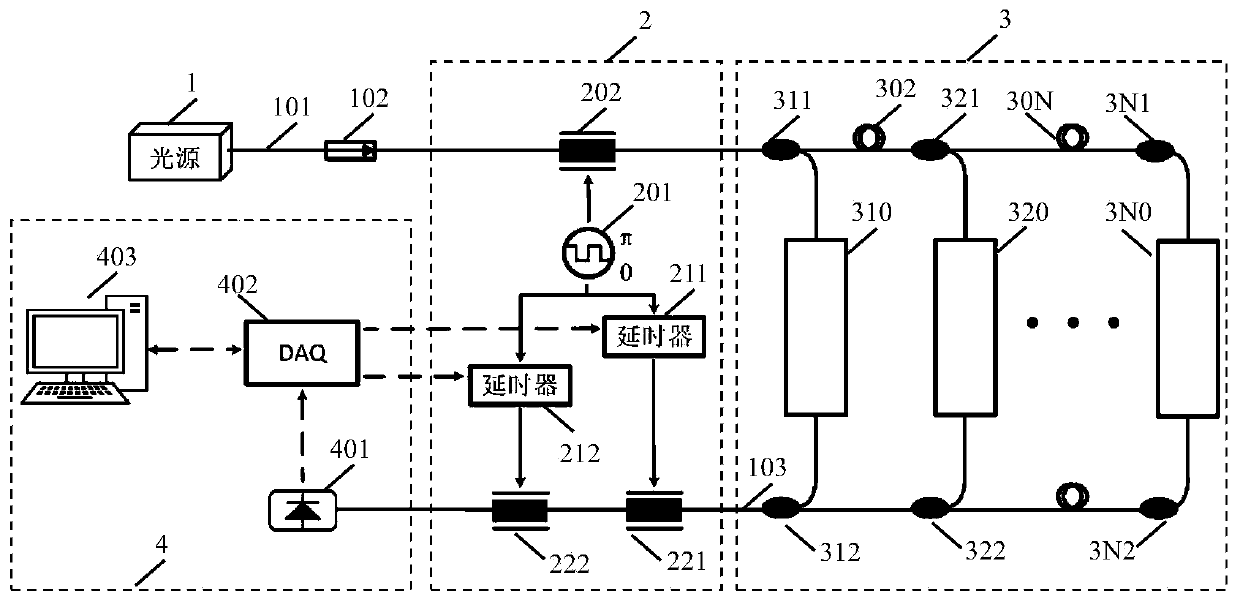
[0062] A four-channel externally modulated Michelson interferometer multiplexing scheme based on pseudo-random codes is attached Figure 4 As shown, it includes four parts: light source 1, pseudo-random code encoding and decoding device 2, four-way optical fiber interferometer cascade array 3, signal detection acquisition and demodulation device 4, and the connection method is as follows:

[0063] 1) The input optical fiber 101 of the light source 1 is successively connected to the isolator 102, the encoder 202 in the pseudo-random code encoding and decoding device 2, and the optical fiber circulator 203, and finally connected to the first optical fiber coupling in the four-way optical fiber interferometer cascaded array 3 device 311;

[0064] 2) The optical fiber circulator 203 in the pseudo-random code encoding and decoding devic...

Embodiment example 2

[0080] Implementation Case 2: A Mach-Zehnder Interferometer Multiplexing Scheme Based on Pseudo-Random Codes for Four-way Light Source Modulation

[0081] A four-way light source modulation Mach-Zehnder interferometer multiplexing scheme based on pseudo-random codes is shown in the attached Figure 5 As shown, it includes four parts: light source 1, pseudo-random code encoding and decoding device 2, four-way optical fiber interferometer cascade array 3, signal detection acquisition and demodulation device 4, and the connection method is as follows:

[0082] 1) The input optical fiber 101 of the light source 1 is successively connected to the isolator 102, the encoder 202 in the pseudo-random code encoding and decoding device 2, and finally connected to the first input optical fiber coupler 311 in the four-way optical fiber interferometer cascaded array 3;

[0083] 2) The first output coupler 312 in the four-way fiber optic interferometer cascaded array 3 is successively connec...


PUM


Abstract

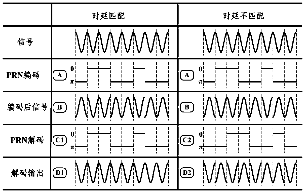
The invention relates to a multi-path optical fiber interferometer multiplexing device and method based on pseudo-random codes, and belongs to the technical field of optical fiber sensing. The devicecomprises four parts including a light source, a pseudo-random code coding and decoding device, a multi-path optical fiber interferometer cascade array, a signal detection acquisition and demodulationdevice. According to the method, a multi-path optical fiber interferometer multiplexing technology is realized by adopting the pseudo-random codes; input optical signals of the array are coded through the pseudo-random codes, and a time delay optical fiber is used for controlling the time delay of each path of the transmitted optical signal; and at the tail end of a transmission optical path, decoding and signal extraction are finished by matching the transmission time delays of all paths of the optical signals. According to the method, the multiplexing integration of the transmitted signalsof the multi-path optical fiber interferometer array of a single optical fiber is realized, so that the complexity of a large-scale multiplexing array transmission optical path system is reduced; andthe pseudo-random codes have sharp autocorrelation and small values of cross-correlation with the noises, so that the noises of the transmission system can be reduced, and the system noise suppressionis realized. The method is suitable for application in large-scale interference type optical fiber sensor arrays.

Description

technical field [0001] The invention belongs to the technical field of optical fiber sensing, and in particular relates to a multiplexing device and method for a multi-channel optical fiber interferometer based on a pseudo-random code. Background technique [0002] Fiber optic interferometer is a common core component of fiber optic sensors. Interferometric fiber optic sensors use phase changes in the optical path to measure physical quantities, including vibration, stress, displacement, speed, etc. Interferometric fiber optic sensors have the characteristics of high sensitivity, good linearity, wide bandwidth, large dynamic range, and a wide range of measurement objects. Typical applications include fiber optic hydrophones, fiber optic seismometers, and fiber optic strain gauges. In practical applications, it is often necessary to cascade a large number of interferometric fiber optic sensors to form an array to realize the function of simultaneous measurement of multi-point...

Claims


Application Information

Patent Timeline
Patent Type & Authority Applications(China)
IPC IPC(8): G01D5/353
Inventor 杨军田帅飞唐乙平张毅博祝海波马驰苑勇贵苑立波
Owner HARBIN ENG UNIV
Why Eureka
Try Eureka