
A measuring device and method for measuring the three-way rigidity of different specifications of foundation supports

A foot and rigidity technology, applied in the field of CNC machine tool design, can solve the problems of long cycle, no application value, high experimental cost, etc., achieve the effects of fast three-way stiffness, real-time monitoring and acquisition, and easy maintenance

Active Publication Date: 2021-03-16
TIANJIN UNIV
View PDF7 Cites 0 Cited by
  • Summary
  • Abstract
  • Description
  • Claims
  • Application Information

AI Technical Summary

Problems solved by technology

At present, the measurement method for the three-way stiffness of the foundation support mainly adopts the modal test test. The specific method is to simplify the foundation support into a pad-mass system, and through the vibration equation and the measured frequency mode shape To find the equivalent stiffness of the block, but this method has high experimental cost and long cycle, and can only be analyzed for a certain kind of foundation support, which does not have good application value

Method used


Image

  • A measuring device and method for measuring the three-way rigidity of different specifications of foundation supports
  • A measuring device and method for measuring the three-way rigidity of different specifications of foundation supports
  • A measuring device and method for measuring the three-way rigidity of different specifications of foundation supports

Examples


Embodiment Construction

[0027] The present invention will be further described in detail below with reference to the accompanying drawings and specific examples. It should be understood that the specific embodiments described herein are merely intended to illustrate the invention and are not intended to limit the invention.

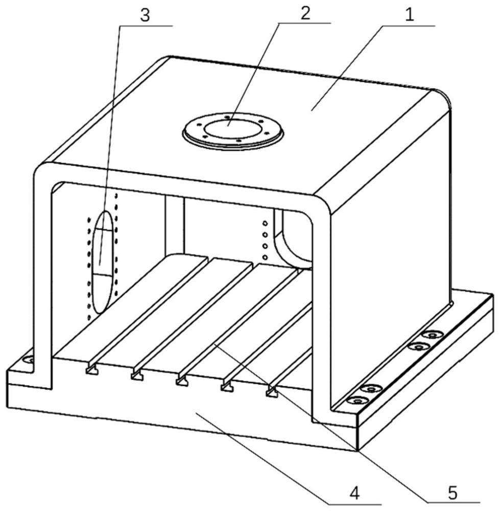
[0028] see figure 1 , The main frame structure of the measuring device is figure 1 As shown, the main frame structure is the platform and foundation of the measuring device, so the reliability of the stiffness is especially important. Therefore, the main frame is integrated with cast steel, and the actual construction of the main frame structure is considered, and the different models is disassembled. The horn is inexpensive, and the process of processing casting, transportation is installed, so that the overall structure of the main frame is designed into the upper and lower parts, and the 12 bolts are used to assemble the two parts. The final body frame is designed with a semi-c...


PUM


Abstract

The invention discloses a measuring device and method for measuring three-way rigidity of foot support of different specifications. The measuring device comprises a main body frame, a normal force loading system, a tangential force loading system, a displacement measuring system and an information collecting system. A semi-sealing structure is adopted by the main body frame which is designed in anupper-lower separation mode, hollow force sensors are arranged in the normal force loading system and the tangential force loading system, loaded real-time monitoring and collecting can be realized,partial uniform transferring can be realized through a pressing block arranged at the tail end of the loading system, and actual foot margin loading is stimulated. The displacement measuring system takes an electrical vortex sensor as a core part, and finally the non-contact measurement and collection of a foot support normal and tangential deformation are realized through information collection.Based on the structure, the quick measurement and accurate analysis of the three-way static rigidity of the foot support of different specifications can be realized, the overall operation is simple, measuring is fast, the result is reliably, and the important pioneering significance is achieved to the successive research of the static rigidity of the foot margin supporting.

Description

Technical field [0001] The present invention relates to the field of CNC machine tools, in particular to a measurement device and measurement method for rapid measurement of different specifications of foot support stiffness. Background technique [0002] Static stiffness is one of the important indicators of machine tool design, and improving the static stiffness of the machine tool is conducive to improving the efficiency, machining accuracy and surface processing quality of the machine. At present, the measurement method of the three-way stiffness is currently supported by the ground foot, mainly using modal test trials, which is to simplify ground foot support into a block-mass block system, through vibration equation and measured frequency vibration To seek equivalents of spacers, and this method has high costs, long cycle, and can only analyze a certain foot support, and does not have good application value. Therefore, the development of a set of normal and tangential loadi...

Claims


Application Information

Patent Timeline
Patent Type & Authority Patents(China)
IPC IPC(8): G01M5/00
Inventor 蒋晓航何改云张大卫张士岳
Owner TIANJIN UNIV
Learn More