
Current/frequency conversion circuit

A frequency conversion circuit and current technology, applied in the direction of adjusting electrical variables, control/regulating systems, instruments, etc., can solve problems such as difficult application and debugging, and achieve the effects of easy implementation, low cost, and simple circuit structure

Active Publication Date: 2019-06-14
XIAN MICROELECTRONICS TECH INST
View PDF4 Cites 25 Cited by
  • Summary
  • Abstract
  • Description
  • Claims
  • Application Information

AI Technical Summary

Problems solved by technology

However, this method is difficult to debug, and it is obtained through linear fitting of a large number of experimental data; at the same time, due to the discreteness of discrete device parameters, it is difficult to apply to engineering practice

Method used


Image

  • Current/frequency conversion circuit
  • Current/frequency conversion circuit
  • Current/frequency conversion circuit

Examples


Embodiment Construction

[0031] In order to enable those skilled in the art to better understand the solutions of the present invention, the following will clearly and completely describe the technical solutions in the embodiments of the present invention in conjunction with the drawings in the embodiments of the present invention. Obviously, the described embodiments are only It is an embodiment of a part of the present invention, but not all embodiments. Based on the embodiments of the present invention, all other embodiments obtained by persons of ordinary skill in the art without making creative efforts shall fall within the protection scope of the present invention.

[0032] It should be noted that the terms "first" and "second" in the description and claims of the present invention and the above drawings are used to distinguish similar objects, but not necessarily used to describe a specific sequence or sequence. It is to be understood that the data so used are interchangeable under appropriate ...


PUM


Abstract

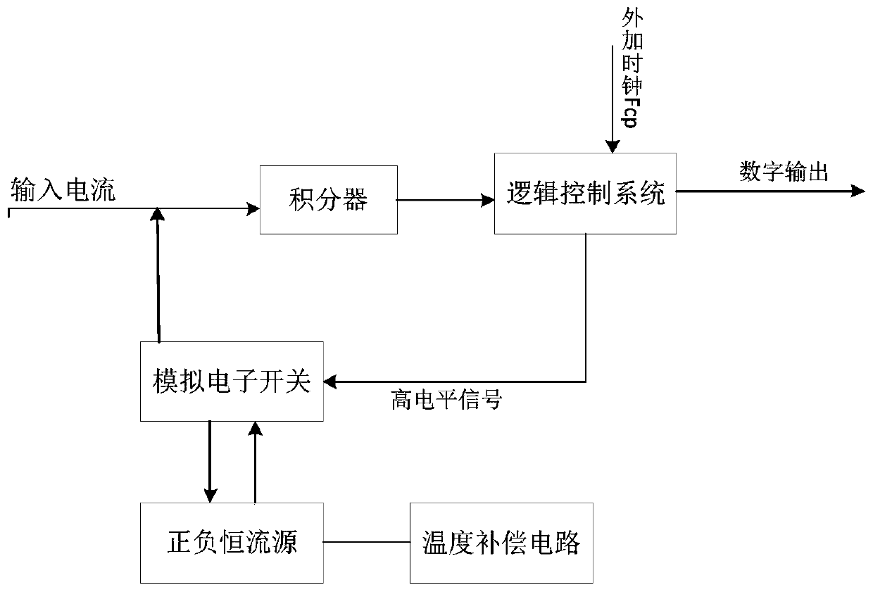
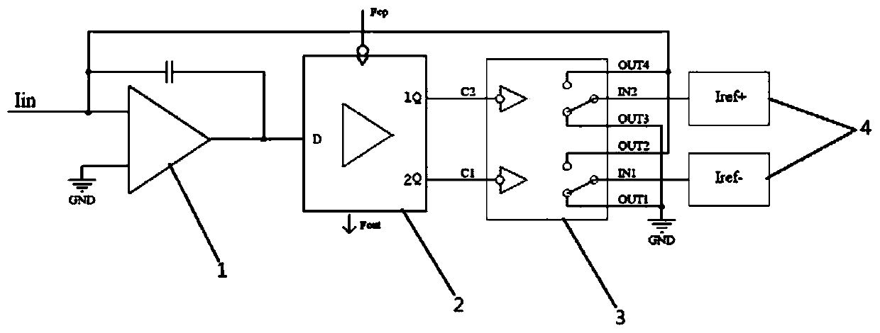
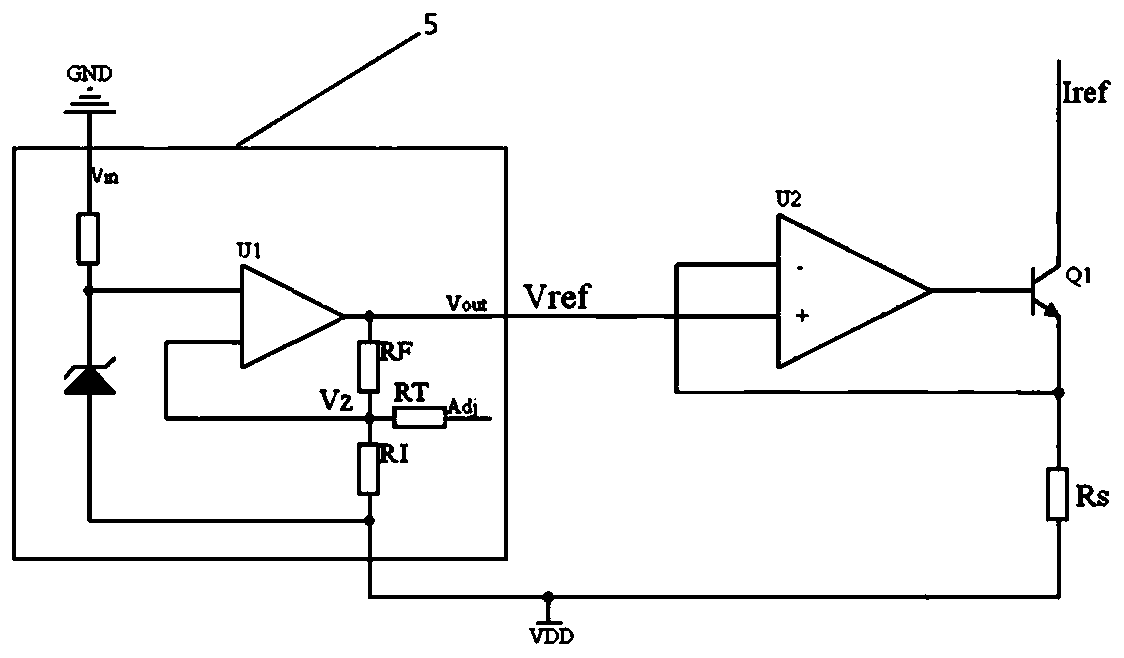
The invention discloses a current / frequency conversion circuit, which comprises an integrator, a logic control circuit, a constant current source, an analog electronic switch and a temperature compensation circuit, wherein the input end of the integrator is connected to the input current, and the output end of the integrator is connected to the logic control circuit; the control signal output endof the logic control circuit is connected to the analog electronic switch, and the logic control circuit is further provided with a digital output end used for outputting a digital pulse frequency anda clock input end used for inputting an external clock; one end of the analog electronic switch is connected to the output end of the constant current source, and the other end of the analog electronic switch is connected to the input end of the integrator; and the temperature compensation circuit is connected to an adjusting port of the constant current source. The reference voltage is directlychanged through the temperature compensation circuit, so that the output of the constant current source is changed, the temperature change of the whole circuit is compensated, and the current / frequency conversion circuit is good in temperature coefficient. The temperature coefficient of the circuit is greatly improved without depending on an index of a single device. Meanwhile, the line structureis simple and the stability of a converter cannot be affected.

Description

technical field [0001] The invention belongs to the field of current / frequency conversion and relates to a current / frequency conversion circuit. Background technique [0002] The current / frequency converter has the characteristics of high resolution and strong anti-interference ability, and is widely used in the conversion of accelerometer and gyro signals in inertial navigation systems. As a circuit for signal conversion, parameters such as better linearity and temperature coefficient are essential. However, changes in the ambient temperature will cause changes in the internal carriers of the semiconductor device, which directly affects the parameter characteristics of the device, and the impact on this high-precision conversion circuit is more obvious. The temperature coefficient of the converter directly affects the temperature coefficient of the scale factor of the system, which affects the navigation accuracy. The temperature coefficient of the current / frequency conve...

Claims


Application Information

Patent Timeline
Patent Type & Authority Applications(China)
IPC IPC(8): G05F1/567
Inventor 黄征郭文娟强冰尹浩黄华王云
Owner XIAN MICROELECTRONICS TECH INST
Learn More