Micro-current amplifier

A micro-current and amplifier technology, applied in the direction of differential amplifiers, DC-coupled DC amplifiers, and electric/magnetic devices to transmit sensing components, etc., can solve the problem of increasing the feedback resistance of current-voltage converters, limiting the bandwidth of micro-current amplifiers, Reduce circuit reliability and other issues to achieve the effect of improving temperature coefficient, increasing bandwidth and improving reliability

Inactive Publication Date: 2009-10-14
CENT FOR SPACE SCI & APPLIED RES
View PDF0 Cites 10 Cited by
  • Summary
  • Abstract
  • Description
  • Claims
  • Application Information

AI Technical Summary

Problems solved by technology

The main disadvantage of this method is that a switch is used at the input end of the micro-current amplifier, which is easy to introduce interference and reduce the reliability of the circuit; in addition, each current-voltage converter still needs a certain degree of stability from open circuit to stable operation. time
And in the above two methods, in order to obtain a large amplifier range and measure weaker signals, it is necessary to increase the feedback resistance of the current-voltage converter, which will further limit the bandwidth of the micro-current amplifier, so it is not suitable for Measuring weak and rapidly changing signals

Method used


Image

  • Micro-current amplifier
  • Micro-current amplifier
  • Micro-current amplifier

Examples


Embodiment Construction

[0024] The present invention will be further described below in conjunction with the accompanying drawings and specific embodiments.

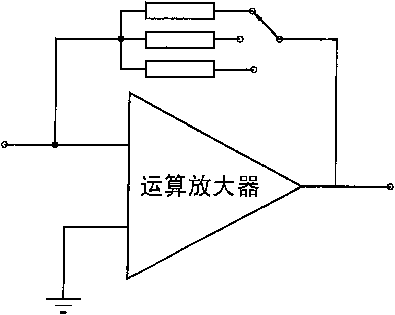
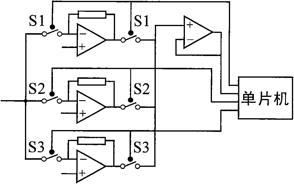
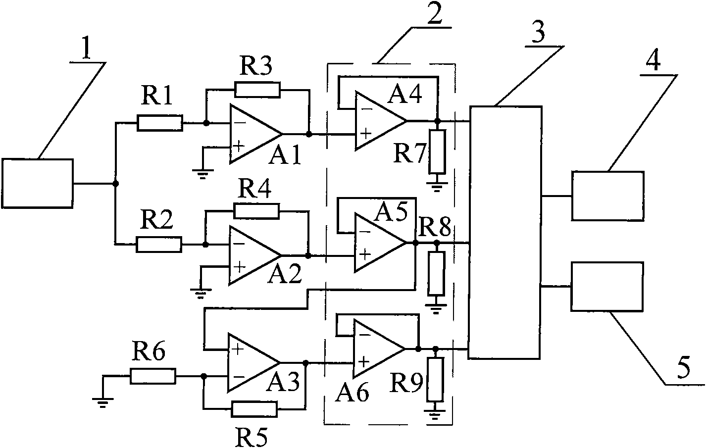
[0025] like image 3 As shown, this embodiment includes a photodetector 1, matching resistors R1, R2, a current-voltage conversion circuit (mainly composed of an operational amplifier and a feedback resistor in this embodiment), a voltage follower component 2, a DC amplifier, and an electronic switch 3 , AD acquisition circuit 4 and single-chip microcomputer 5.

[0026] The micro-current output of the photodetector 1 is supplied to one current-voltage conversion circuit through the matching resistor R1, and is supplied to another current-voltage conversion circuit through the matching resistor R2. The photodetector 1 can be a photomultiplier tube or a photodetector with other current sources. In this embodiment, an R7111-01 photomultiplier tube is used. For micro current, the photomultiplier tube has the characteristics of high gain, fast spe...


PUM


Abstract

The invention provides a micro-current amplifier comprising a plurality of micro-current amplification branch circuits with different gains and a multipath electronic switch connected with the micro-current amplification branch circuits, wherein each micro-current amplification branch circuit comprises a photodetector, a matched resistor and a current-voltage converting circuit which are sequentially connected; and part of the micro-current amplification branch circuits also comprises DC amplifiers, and the input ends of the DC amplifiers are connected with the output ends of the current-voltage converting circuits. The invention has the advantages of low disturbance and high circuit reliability, and the like and can measure a rapidly changed weak signal in a wide range.

Description

technical field [0001] The invention relates to a detection signal amplifier, in particular, the invention relates to a micro current amplifier. Background technique [0002] The micro current amplifier is used to amplify the signal of the current output photodetector. At present, micro-current amplifiers usually use current-voltage converters, and increase their range by changing the feedback resistance, such as figure 1 Shown (see reference: Shimadzu Gas Chromatography FID Micro-current Amplifier and Polarized Voltage Source Circuit Board Analysis, Foreign Analytical Instrument Technology and Application, 1992, No. 1, p36-39). The main disadvantage of this method is that it takes a certain time to establish and stabilize the micro-current amplifier with different feedback resistors, and it is not suitable for the situation where the detection signal changes rapidly in a large range. [0003] Another way to increase the range of the micro-current amplifier is to use multi...

Claims


Application Information

Patent Timeline
Patent Type & Authority Applications(China)
IPC IPC(8): G01D5/14H03F3/45
Inventor 王英鉴陈济张仲谋王咏梅吕建工王永松
Owner CENT FOR SPACE SCI & APPLIED RES
Why Eureka
Try Eureka