Tunable filter and tunable duplexer

A filter and waveguide resonance technology, which is applied in the field of adjustable filters and adjustable duplexers, can solve the problems of increasing filter insertion loss, volume, weight and cost, etc., and achieves low production cost, simple structure, The effect of good out-of-band rejection characteristics

Pending Publication Date: 2019-06-14
PIVOTONE COMM TECH
View PDF2 Cites 3 Cited by
  • Summary
  • Abstract
  • Description
  • Claims
  • Application Information

AI Technical Summary

Problems solved by technology

Adding a resonant cavity means increasing the insertion loss of the filter, and the volume, weight and cost will all increase

Method used


Image

  • Tunable filter and tunable duplexer
  • Tunable filter and tunable duplexer
  • Tunable filter and tunable duplexer

Examples


Embodiment 1

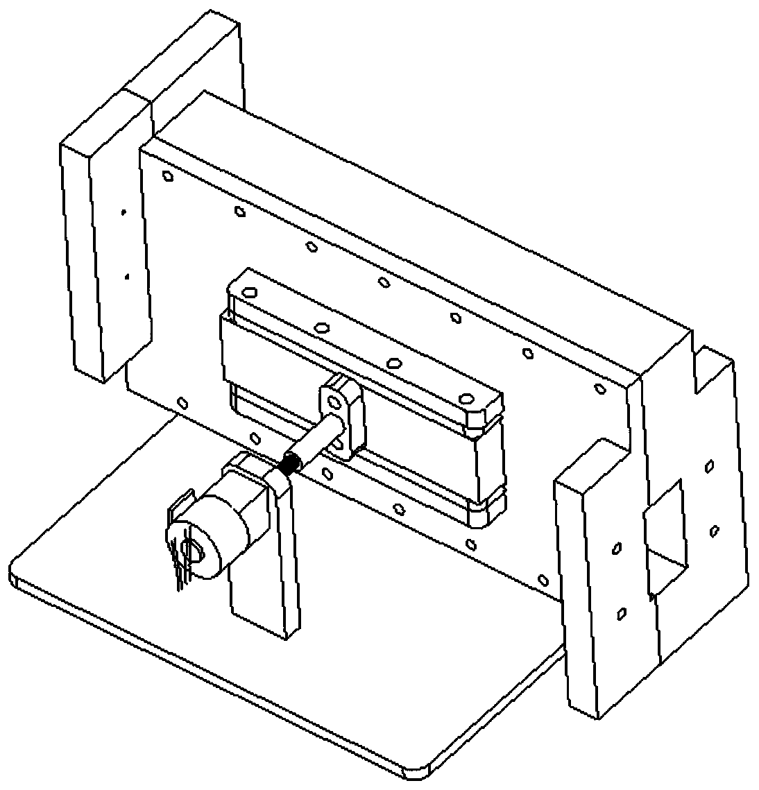
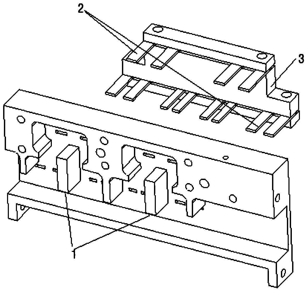
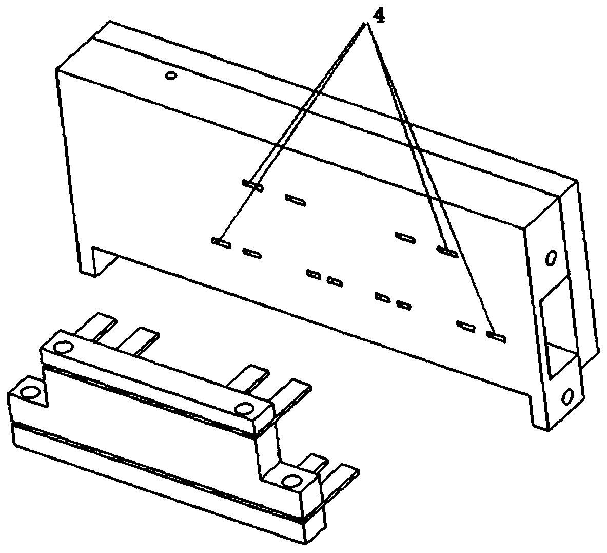
[0040] The tunable filter of this embodiment is a tunable filter with sixth-order two zeros, and its basic structure is as follows Figure 1~3 shown, including cavity and tuning mechanism. Such as figure 2 , 3 As shown, the cavity is composed of a matching frame and cover plate, which contains 6 waveguide resonators. The direct coupling between adjacent waveguide resonators is realized through the direct coupling window. The first non-adjacent waveguide Between the resonator and the third waveguide resonator, and between the fourth waveguide resonator and the sixth waveguide resonator, positive cross-coupling is realized through the cross-coupling structure 1 composed of cross-coupling windows; image 3 As shown, at least one slit 4 is opened on the same side cavity wall of each waveguide resonant cavity, and the electrical length of each slit 4 is less than the half-wavelength of the highest operating frequency of the tunable filter, so that electromagnetic waves can be comp...

Embodiment 2

[0044] The tunable filter structure of this embodiment is basically the same as that of Embodiment 1, the difference lies in that a negative cross-coupling structure is added on the basis of Embodiment 1. Such as Figure 4 As shown, the negative cross-coupling structure 1 of this embodiment realizes negative cross-coupling at the same time by setting a metal post at the cross-coupling window, the bottom of the metal post is connected to the bottom of the cavity of the filter, and the top of the metal post is connected to the filter cavity. The cover plate of the device does not touch, there is a certain distance. The metal post can be fixed on the bottom of the cavity, or electrically connected to the bottom of the cavity through some adjustable structure, so that the distance between the top of the metal post and the cover plate of the filter can be adjusted. When the dielectric sheet is not inserted, the negative cross-coupling coefficient can be adjusted by adjusting the d...


PUM


Abstract

The invention discloses a tunable filter, which comprises a cavity and a tuning mechanism. At least three waveguide resonant cavities are arranged in the cavity, direct coupling is realized between adjacent waveguide resonant cavities through a direct coupling window, cross coupling is realized between non-adjacent waveguide resonant cavities through a cross coupling structure, at least one slit is arranged on the cavity wall at the same side of each waveguide resonant cavity, and the electrical length of each slit is less than the half-wavelength of the highest working frequency of the tunable filter; the tuning mechanism comprises a group of dielectric sheets and a driving mechanism, wherein the dielectric sheets are in one-to-one correspondence with the slits, and all the dielectric sheets can be simultaneously inserted into the corresponding waveguide resonant cavities at the same depth without friction through the corresponding slits under the driving of the driving mechanism. Theinvention also discloses a tunable duplexer. The tunable filter and the tunable duplexer have good out-of-band rejection characteristic, and in the whole tuning range, the relative position of the transmission zero and the bandwidth of the pass band is basically kept unchanged, and the echo of the filter is kept at a better level.

Description

technical field [0001] The invention relates to a filter, in particular to an adjustable filter and an adjustable duplexer. Background technique [0002] Tunable filters are an important part of microwave reconstruction systems, and are widely used in frequency hopping radio stations, electronic countermeasures, multifunctional receivers, dynamic frequency allocation systems, and point-to-point communication systems. The use of adjustable filters can greatly reduce the material and maintenance costs of communication equipment manufacturers. Taking point-to-point communication as an example, an adjustable filter can replace dozens of conventional filters, so it can greatly reduce the number of types of ODU equipment. Greatly reduce production, storage, transportation and maintenance costs. Therefore, it is a hot research field in the microwave communication industry at present. Common tunable filters are mostly realized by means of radio frequency switches to control loadin...

Claims


Application Information

Patent Timeline
Patent Type & Authority Applications(China)
IPC IPC(8): H01P1/208
Inventor 江顺喜彭海璐梁国春殷实周方平张丽玲项显
Owner PIVOTONE COMM TECH
Why Eureka
Try Eureka