Self-input control load modulation type power amplifier and implementation method thereof

A power amplifier and load modulation technology, which is applied in the field of wireless communication, can solve the problems of complex modulation methods and low efficiency, and achieve the effect of increasing the working bandwidth and improving the range of high-efficiency power fallback

Active Publication Date: 2019-06-14
HANGZHOU DIANZI UNIV
View PDF4 Cites 6 Cited by
  • Summary
  • Abstract
  • Description
  • Claims
  • Application Information

AI Technical Summary

Problems solved by technology

Although conventional power amplifiers, as combined class AB, exhibit very low efficiency at power back-off, widely adopted efficiency enhancement techniques such as load modulation techniques represented by Doherty and Chireix keep their efficiency high at power back-off
[0003] But with the rapid development of communication technology, modulation methods are becoming more and more complex, and the narrowband characteristics of traditional Doherty and Chireix modulation power amplifiers are increasingly unable to meet today's wireless Therefore, it is urgent to develop a new type of RF power amplifier with wideband and high power back-off range to meet the high transmission rate requirements of current and future wireless communication systems.

Method used


Image

  • Self-input control load modulation type power amplifier and implementation method thereof
  • Self-input control load modulation type power amplifier and implementation method thereof
  • Self-input control load modulation type power amplifier and implementation method thereof

Examples


Embodiment Construction

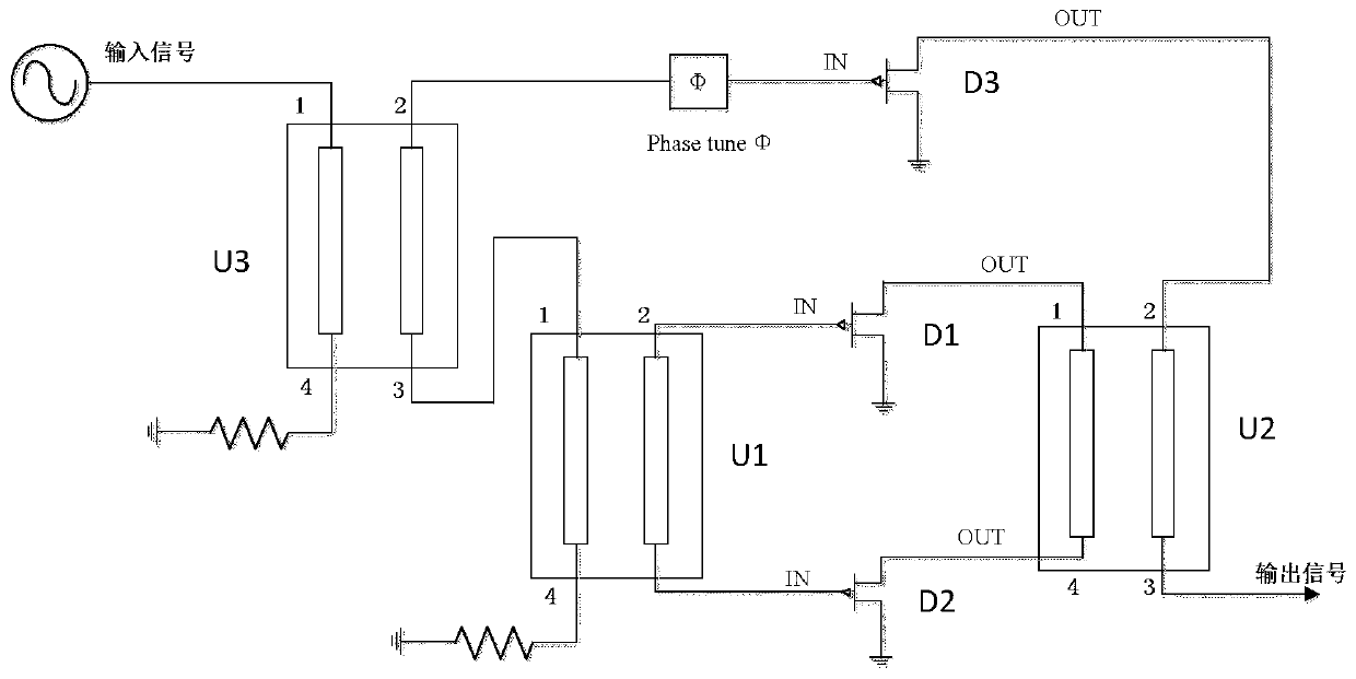
[0030] Such as figure 1 As shown, a method for realizing a self-input-controlled load modulation power amplifier specifically includes the following steps:

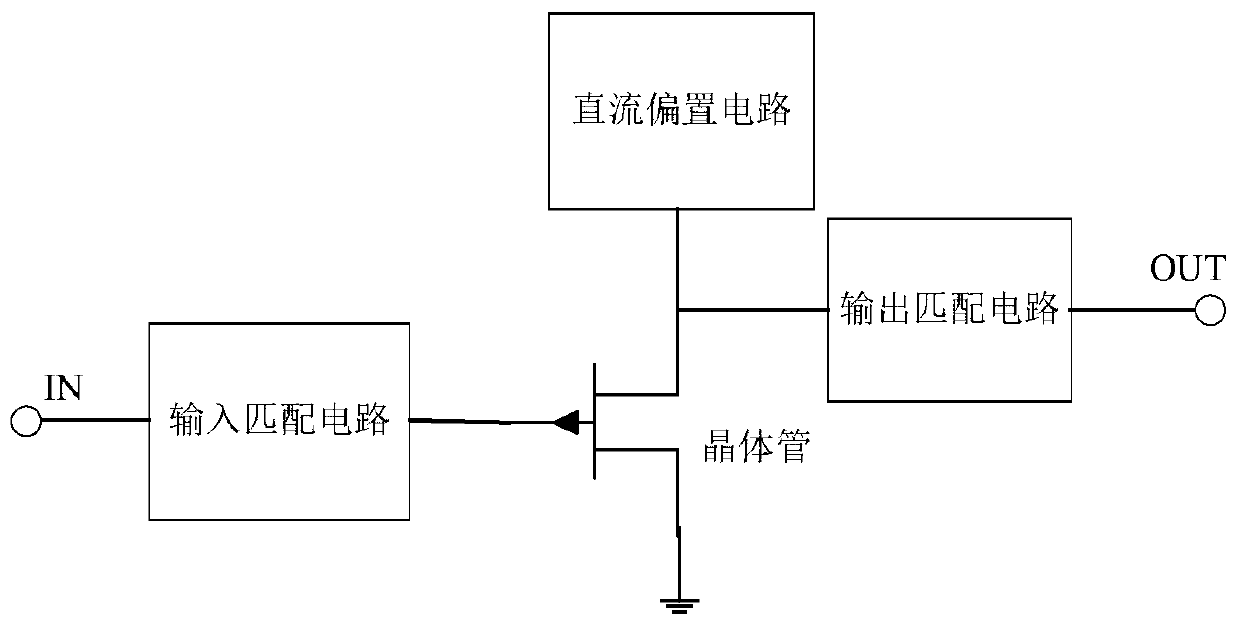
[0031] Step 1: According to the selected transistor (such as CGH40010F GaN HEMT) use such as Figure 4 For the DC characteristic scanning curve shown, the drain bias voltage is 28V, and the gate bias voltage is -2.7V so that the transistor is in a linear amplification state. At this time, the conduction angle of the transistor is between π and 2π, which meets the conduction angle requirements of the class AB power amplifier. On the basis of this DC bias, the input and output matching circuit is designed for the transistor. In order to expand the operating bandwidth of the circuit, the matching circuit adopts step impedance matching design. Match the input and output impedance of the transistor to the standard load impedance of 50 ohms, the topology of the power amplifier circuit is as follows figure 2 shown. Select ...


PUM


Abstract

The invention relates to a self-input control load modulation type power amplifier and an implementation method thereof. An input signal is equally divided into two paths by a third orthogonal coupler. The first quadrature coupler converts one path of output signal into two paths of quadrature signals through the power amplification circuit and outputs the two paths of quadrature signals, and thesignals output by the two paths of power amplification circuits are connected to the input end of the second quadrature coupler and then output to a load. And a required control signal is accessed tothe isolation end of the second orthogonal coupler for load modulation. And the control signal is realized by performing phase adjustment and power amplification on the other path of output signal. The load modulation type power amplifier is realized by introducing a control signal into a quadrature coupler. The control signal generates required amplitude and phase control signals through the control signal generation circuit according to requirements, so that the working bandwidth of the load modulation type power amplifier is increased, and the efficiency of the load modulation type power amplifier within the power back-off range is improved.

Description

technical field [0001] The invention belongs to the technical field of wireless communication, and relates to a self-input controlled load modulation power amplifier and a realization method thereof. Background technique [0002] With the rapid development of wireless communication technology, radio frequency microwave technology is becoming more and more important in people's daily life. Modern wireless communication standards rely on modulated signals characterized by high spectral efficiency in order to optimize the use of scarce spectral resources. From a high-frequency transmitter point of view, this choice leads to stringent requirements on linearity, accompanied by a very high peak-to-average power ratio (PAPR) of the signal from the power amplifier (PA). Although conventional power amplifiers, as combined class AB, exhibit very low efficiency at power back-off, widely adopted efficiency enhancement techniques such as load modulation techniques represented by Doherty...

Claims


Application Information

Patent Timeline
Patent Type & Authority Applications(China)
IPC IPC(8): H03F1/02H03F3/21
CPCY02D30/70
Inventor 程知群张志维刘国华柯华杰李素东杨仁好
Owner HANGZHOU DIANZI UNIV
Why Eureka
Try Eureka