Biomass toothed pressing wheel rolling-type forming machine and forming method

A molding machine and biomass technology, applied in the direction of material molding presses, presses, manufacturing tools, etc., can solve the problems of short mold life, low production efficiency, high production cost, etc., and achieve convenient maintenance and replacement of parts, mold Long life and energy saving effect

Pending Publication Date: 2019-06-18
沈阳燃料设备制造安装有限公司
View PDF0 Cites 1 Cited by
  • Summary
  • Abstract
  • Description
  • Claims
  • Application Information

AI Technical Summary

Problems solved by technology

[0005] Aiming at the disadvantages of the prior art, such as high energy consumption, high production cost, low production efficiency, and severe equipment wear during the production process, resulting in short mold life, the purpose of the present invention is to provide a biomass tooth Shaped pressure wheel rolling forming machine and forming method, compared with the traditional structure, the forming machine structure is relatively simple, easy maintenance, convenient operation, stable product quality, low energy consumption, especially the life of the mold is greatly extended, and its forming method Wide applicability of raw materials and stable product quality

Method used


Image

  • Biomass toothed pressing wheel rolling-type forming machine and forming method
  • Biomass toothed pressing wheel rolling-type forming machine and forming method
  • Biomass toothed pressing wheel rolling-type forming machine and forming method

Examples


Embodiment 1

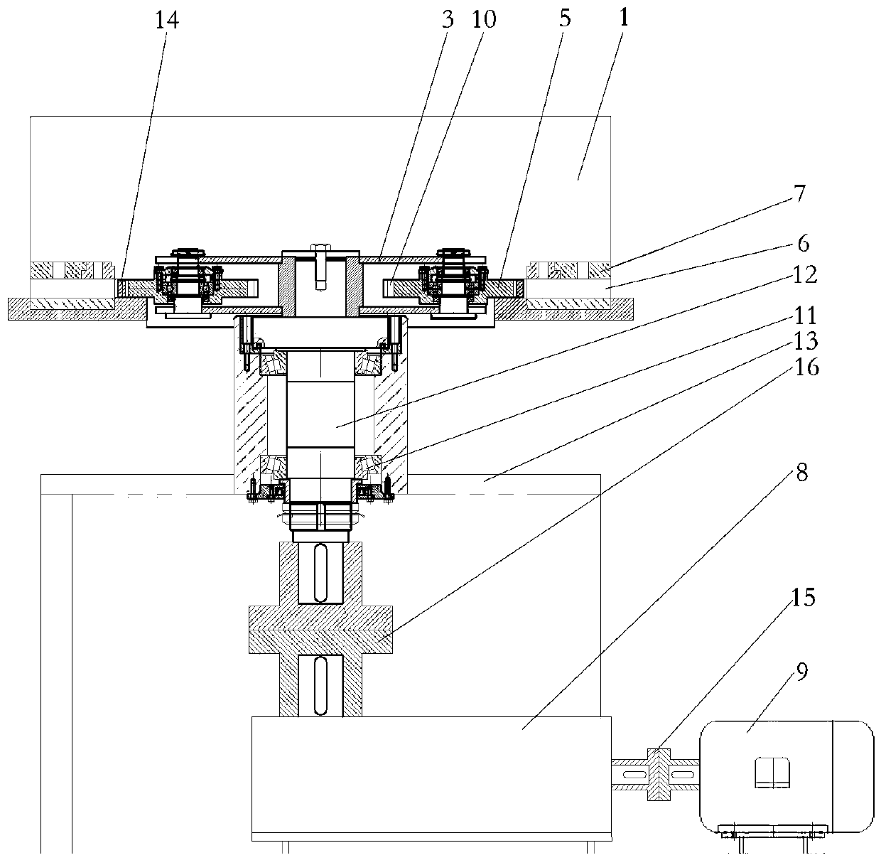
[0036] Embodiment 1: The present invention includes a machine base (13), a feed bin (1), a transmission spindle (12), an extrusion device, an annular fixed mold (7) and a driving device, and a driving device is provided in the hollow of the machine base (13). The drive device is mainly composed of a reducer (8) and a drive motor (9). One end of the reducer (8) is connected to the drive shaft (12) through the second coupling (16), and the other end is connected through the first The shaft coupling (15) is connected with the driving motor (9);

[0037] A silo (1) is arranged above the machine base (13), and the transmission main shaft (12) is fixed in the hollow of the machine base (13) through at least two sets of bearings (11) in the axial and radial directions to ensure that the transmission main shaft (12) ) operates stably when subjected to two-way force;

[0038] The lower end of the transmission spindle (12) is connected with the reducer (8), and the upper end is connect...

Embodiment 2

[0044] Embodiment 2: A water jacket (4) can also be provided on the outside of the silo (1) of the present invention. The water jacket (4) is located on the upper part of the annular fixed mold (7). The water jacket (4) passes through the through hole and feeds The area is connected; it is to prevent the dense raw material from clogging the cavity (6) when the machine is shut down, that is, to send an appropriate amount of water into the material area through the water jacket (4) before the machine is shut down, so that the raw material that is about to enter the cavity contains excessive water To ensure that the raw material staying in the mold cavity (6) is in a loose state with high moisture content and cannot be molded in the mold cavity, so that the mold cavity (6) will not be blocked during the next startup. If it is not used for a long time, the raw materials in the cavity (6) need to be cleaned up, and the loose raw materials are easy to clean.

Embodiment 3

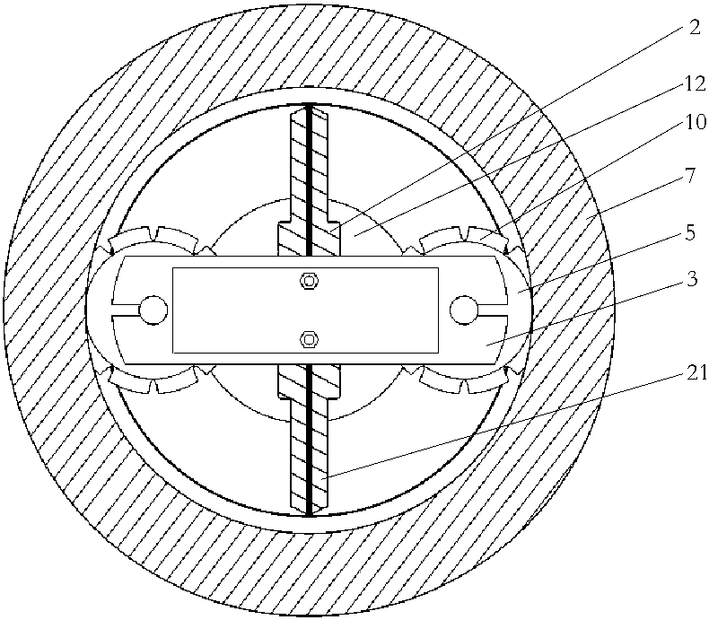
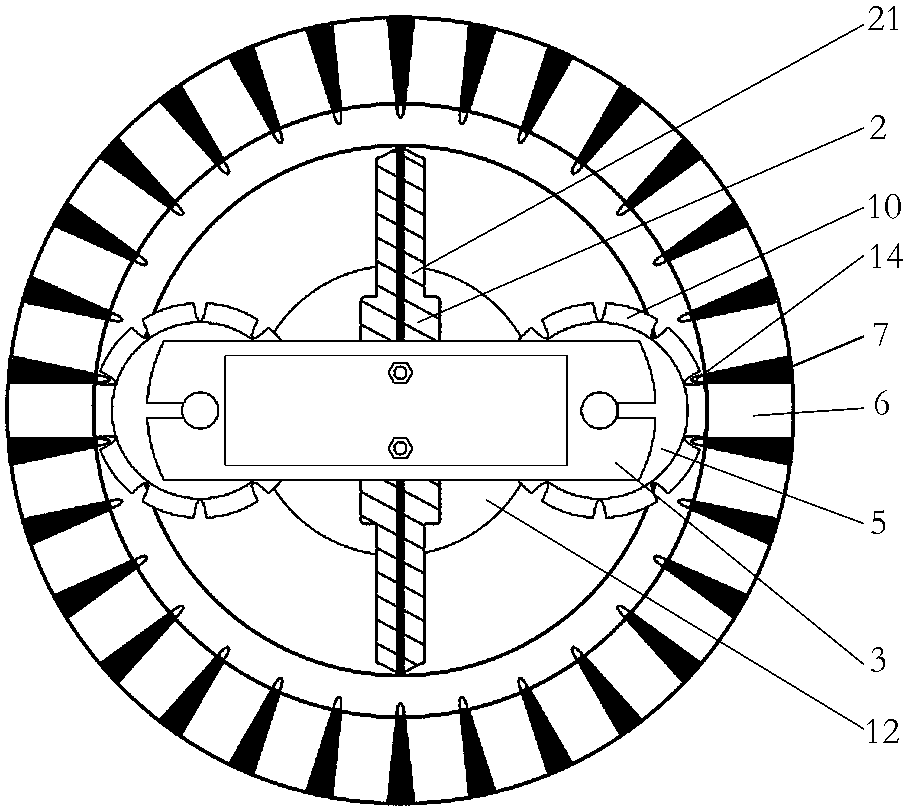
[0045] Embodiment three: the outlet of the mold cavity (6) of the outer circumference of the ring-shaped fixed mold (7) can also be provided with a fixed-length baffle, and the fixed-length baffle is arranged on the outer circumference of the ring-shaped fixed mold in a ring. Keep compression molded products at a uniform length. That is, when the main shaft (12) rotates, the rotating bracket (3) and the toothed pressure wheel (5) start to roll, and the raw material in front of each pressure wheel tooth (10) is pressed into the front cavity (6), and the feeding device ( 2) Continuously feed the raw material into the gap between the pinch wheel teeth (10) and the annular fixed mold (7), the rotating bracket (3) and the toothed pinch wheel (5) run continuously, and the annular fixed mold (7) Stable extrusion of dense straw blocks at the outlet of the die cavity on the outer circumference. In order to prevent the straw blocks from automatically falling due to their own weight, a l...


PUM


Abstract

The invention discloses a biomass toothed pressing wheel rolling-type forming machine. The biomass toothed pressing wheel rolling-type forming machine comprises a machine seat, a material bin, a transmission spindle, an extrusion device, an annular fixed mold and a driving device, the machine seat is provided with a hollow part, the hollow part of the machine seat is internally provided with the driving device, the material bin is arranged above the machine seat, the transmission spindle is fixed into the hollow part of the machine seat through two or more sets of bearings in axially and radially positioned modes, the lower end of the transmission spindle is connected with the driving device, the upper end of the transmission spindle is connected with the extrusion device, the extrusion device is connected to the transmission spindle in a sleeving mode and located on the upper part of the machine seat, both a feeding device and the extrusion device rotate along with the transmission spindle, the annular fixed mold is arranged at the position, corresponding to the extrusion device, of the lower part of the material bin, the annular fixed mold is fixed to the position above the machine seat, and the annular fixed mold and the extrusion device are connected in an engaged mode. The biomass toothed pressing wheel rolling-type forming machine is simple in structure, convenient to maintain, convenient to operate, stable in product quality, capable of realizing energy saving, long in mold life, and a forming method of the biomass toothed pressing wheel rolling-type forming machineis wide in raw material applicability.

Description

technical field [0001] The invention belongs to the field of biomass new energy processing machinery, and in particular relates to an improvement in the structure of a molding machine for biomass fuel blocks. Background technique [0002] Biomass new energy is to convert a wide range of biomass wastes, such as: crop straw, shells and skins discarded from agricultural product processing, wood chips, branches and branches, and combustible parts of domestic waste, etc. The characteristic fuel makes it a new energy product that can easily replace traditional fossil fuels - straw fuel block. [0003] At present, the existing agricultural straw includes corn straw, wheat straw, rice straw, oil crop straw, soybean and wheat crop straw, miscellaneous grain straw, cotton straw, branch wood, etc. It is the fourth largest energy source after coal, oil and natural gas. It accounts for 14% of the world's total energy consumption. The annual output of crop straw in my country is about 7...

Claims


Application Information

Patent Timeline
IPC IPC(8): B30B11/20B30B15/00B30B15/30B30B15/02
Inventor 陈坚马骏姜铁英姚建华
Owner 沈阳燃料设备制造安装有限公司
Why Eureka
Try Eureka