Eureka AIR delivers breakthrough ideas for toughest innovation challenges, trusted by R&D personnel around the world.

Automatic adhesion equipment for marking rod protection cloth of road traffic denoter

A technology for road traffic and sign poles, which is applied in the field of automatic adhesion equipment for sign pole protection cloth, can solve the problems of low cloth wrapping efficiency, time-consuming and labor-intensive, etc., and achieve the effect of improving work efficiency

Active Publication Date: 2019-06-18
HUZHOU COLLEGE
View PDF7 Cites 0 Cited by
  • Summary
  • Abstract
  • Description
  • Claims
  • Application Information

AI Technical Summary

Problems solved by technology

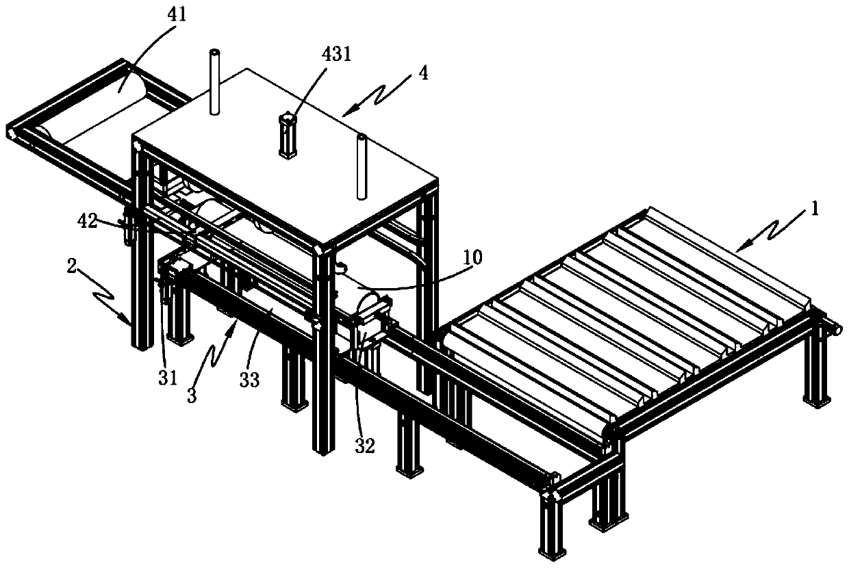
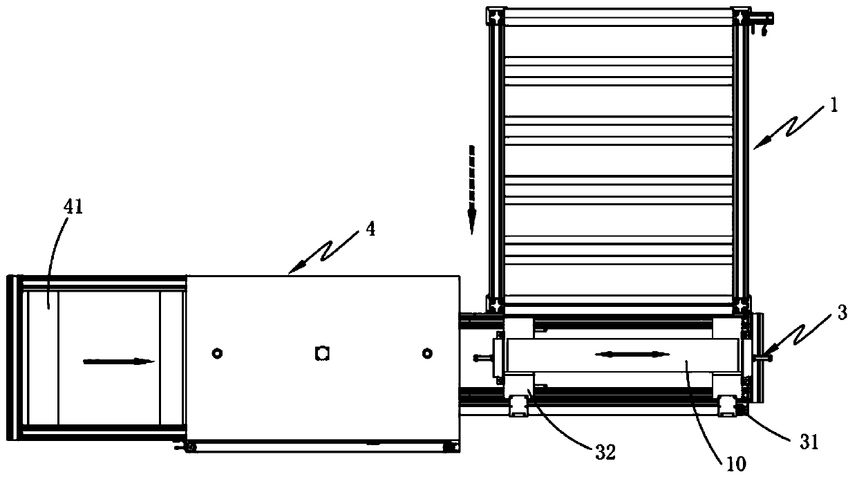
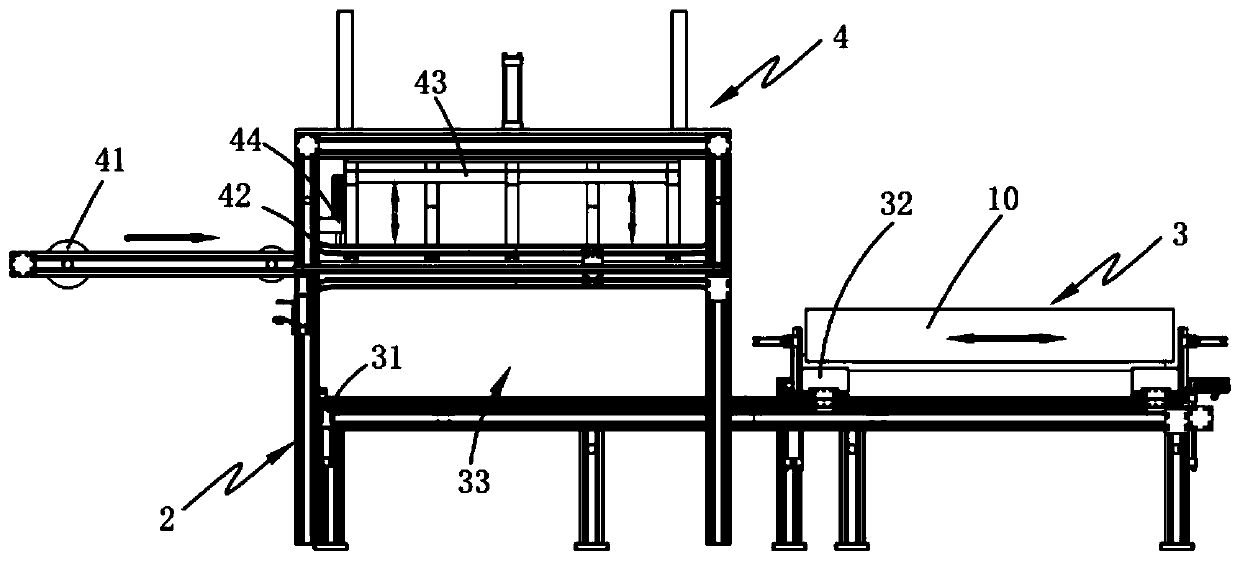
[0004] Aiming at the deficiencies of the prior art, the present invention provides an automatic adhesion equipment for the protective cloth of the road traffic signs. By setting the cloth adhesion device, the sign pole limiting device transports the sign pole to the bottom of the cloth adhesion device and The clamping and pulling component lays the cloth evenly in the cloth clamping and laying area above the sign pole under the rotary clamping, and realizes the glue coating on both ends of the cloth while laying the cloth, and then the adhesive component is used for both ends of the cloth. Covering and adhering successively on the surface of the sign post realizes the integration of automatic transportation, cover and adhesion of the sign post, replaces the original manual covering method, greatly improves the work efficiency, and solves the problem of manual wrapping in the prior art Time-consuming and labor-intensive, technical problems of low winding efficiency

Method used


Image

  • Automatic adhesion equipment for marking rod protection cloth of road traffic denoter
  • Automatic adhesion equipment for marking rod protection cloth of road traffic denoter
  • Automatic adhesion equipment for marking rod protection cloth of road traffic denoter

Examples


Embodiment 1

[0072] Embodiments of the present invention are described in detail below, examples of which are shown in the drawings, wherein the same or similar reference numerals designate the same or similar elements or elements having the same or similar functions throughout. The embodiments described below by referring to the figures are exemplary and are intended to explain the present invention and should not be construed as limiting the present invention.

[0073] Such as figure 1 , 2 , 3, 4 and 5, an automatic adhesion equipment for the protective cloth of a sign pole of a road traffic sign, including a feeding device 1, a frame 2, and also includes:

[0074] Marking rod limiting device 3, the marking rod limiting device 3 is arranged on the frame 2, and the feeding end of the marking rod limiting device 3 is located on the side of the output end of the feeding device 1, the marking The rod limiter 3 includes a feed transport assembly 31, a lift limit assembly 32 slidably arrange...


PUM


Abstract

The invention provides automatic adhesion equipment for the marking rod protection cloth of a road traffic denoter. The automatic adhesion equipment comprises a feeding device, a machine frame, a making rod limiting device and a cloth adhesion device, the marking rod limiting device is arranged on the machine frame, the feeding end of the marking rod limiting device is located on one side of the output end of the feeding device, the marking rod limiting device comprises a feeding transporting assembly, and a lifting limiting assembly, the cloth adhesion device is arranged above a coating areaand comprises a cloth conveying assembly, a clamping and cloth pulling assembly, and an adhesion assembly, the marking rod limiting device transports the marking rod below the cloth adhesion device sothat the cloth is flatly paved in a cloth clamping and paving area above the marking rod under the rotary clamping of the clamping and cloth pulling assembly, the glue coating at the two ends of thecloth is achieved while cloth pulling and paving are achieved, sequential cladding and adhesion of the two ends of the cloth on the surface of the marking rod by the adhesion assembly are achieved, the original manual cladding manner is replaced, and the problem of the low cloth winding efficiency in the prior art is solved.

Description

technical field [0001] The invention relates to the field of production and manufacture of road traffic indicating equipment, in particular to an automatic adhesion device for a protective cloth of a signpost of a road traffic signboard. Background technique [0002] Traffic signs guide vehicles on the road to ensure traffic order. Common traffic sign poles include fixed poles, beams and signs. The structure is very unbalanced, and a pole with sufficient strength is required. In addition, if maintenance and replacement of signboards are required, mechanical equipment must be used to climb up, and maintenance in the middle of the road will endanger the lives of maintenance personnel. [0003] When the traditional traffic sign poles are manufactured, they are firstly welded manually, and then the welds are polished after the welding is completed. After the grinding is completed, the sign poles are transported to the hydrochloric acid pool by the sign pole transportation device...

Claims


Application Information

Patent Timeline
Patent Type & Authority Applications(China)
IPC IPC(8): B65B33/02B65B61/06
Inventor 郝利峰
Owner HUZHOU COLLEGE
Why Eureka
Eureka Blog
Learn More