
Material rack and copper tube vacuum annealing furnace

A material rack and material technology, which is applied in the field of material rack and copper tube vacuum annealing furnace, can solve the problems of high energy consumption, slow heating speed and energy consumption of the copper tube vacuum annealing furnace, so as to ensure the airflow passing efficiency and heating efficiency. High efficiency and the effect of reducing annealing time

Pending Publication Date: 2019-06-18
ZHEJIANG HAILIANG
View PDF0 Cites 0 Cited by
  • Summary
  • Abstract
  • Description
  • Claims
  • Application Information

AI Technical Summary

Problems solved by technology

[0003] The material frame of the existing copper tube vacuum annealing furnace is welded with a stainless steel frame structure. It is heavy, and a large amount of energy is required for each temperature rise of the material frame. This part of unnecessary energy consumption leads to high energy consumption of the copper tube vacuum annealing furnace, and The heating in the furnace relies on radiation and conduction, and the heating speed is slow, which is another factor that consumes energy

Method used


Image

  • Material rack and copper tube vacuum annealing furnace
  • Material rack and copper tube vacuum annealing furnace
  • Material rack and copper tube vacuum annealing furnace

Examples


Embodiment 1

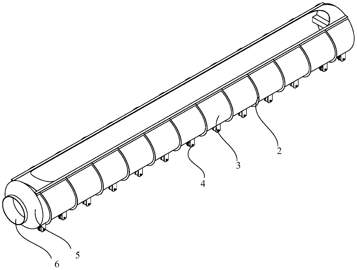
[0030] Please refer to figure 1 , the present embodiment provides a material rack, which includes a cover plate 1 , a spoiler 2 , a material rack body 3 , traveling rollers 4 , a tapered pipe 5 and a suction channel 6 .

[0031] The material rack body 3 is a hollow cylinder with openings at both ends. The openings at both ends of the material rack body 3 are respectively connected to the suction channel 6 and the air inlet channel 8. A material inlet and outlet is also provided on the peripheral wall of the material rack body 3. In this embodiment The material inlet and outlet are set above the material rack body 3, and the material inlet and outlet are connected to the inside of the material rack body 3. The cover plate 1 is arranged on the material inlet and outlet to close the material inlet and outlet. The cover plate 1 and the material The frame body 3 is detachably connected, or covered on the material inlet and outlet, so that the material frame body 3 forms a semi-clos...

Embodiment 2

[0041] This embodiment provides a copper tube vacuum annealing furnace, including a furnace, a centrifugal fan and the above-mentioned material rack, the centrifugal fan is arranged on the furnace, the material rack is arranged in the furnace, and the suction channel 6 of the material rack is arranged on On one side of the centrifugal fan, the air outlet of the centrifugal fan is docked with the suction channel 6 of the material rack.

[0042] The copper tube vacuum annealing furnace of the present embodiment is used for the annealing treatment of the copper tube. The copper tube to be annealed is placed in the material rack body 3, the cover plate 1 of the material rack is covered, and the material rack is put into the purple copper tube. In the furnace of the copper tube vacuum annealing furnace, the centrifugal fan is set on the furnace, the air outlet of the centrifugal fan is connected with the suction channel 6 of the material rack, and the walking roller 4 of the materia...


PUM


Abstract

The invention provides a material rack and a copper tube vacuum annealing furnace and belongs to the technical field of vacuum annealing devices. The material rack comprises a material rack body and acover plate. The material rack body is internally hollow, and the two ends of the material rack body are provided with openings communicating with the internal hollow space. The openings of the two ends of the material rack body communicate with a suction channel and an air outlet channel correspondingly. The material rack body is of a hollow cylindrical structure. The sidewall of the material rack body is provided with a material inlet / outlet. The cover plate is detachably arranged on the material inlet / outlet in a covering mode. The sectional area of an opening of the suction channel of thematerial rack body is less than that of a shaft of the material rack body. A plurality of spoilers are arranged on the peripheral wall of the material rack body. According to the material rack, hot gas in a furnace pipe is forced to get into an air inlet channel of the material rack through a centrifugal fan externally connected with the suction channel and flow out from the suction channel of the material rack, so that the furnace pipe conducts radiation heating, heat transfer heating and gas convection heating on materials in the machine rack. The heating efficiency is high. Energy consumption is small. The containing space of the material rack is large. The gas flow passing efficiency is ensured well.

Description

technical field [0001] The invention relates to the technical field of vacuum annealing devices, in particular to a material rack and a copper tube vacuum annealing furnace. Background technique [0002] The copper tube vacuum annealing furnace is the main equipment for the annealing production of copper tubes, and it is also the focus of energy consumption. [0003] The material frame of the existing copper tube vacuum annealing furnace is welded with a stainless steel frame structure. It is heavy, and a large amount of energy is required for each temperature rise of the material frame. This part of unnecessary energy consumption leads to high energy consumption of the copper tube vacuum annealing furnace, and The heating in the furnace relies on radiation and conduction, and the heating speed is slow, which is also another factor that consumes energy. Contents of the invention [0004] The object of the present invention is to provide a rack and a copper tube vacuum ann...

Claims


Application Information

Patent Timeline
Patent Type & Authority Applications(China)
IPC IPC(8): C21D9/08C22F1/08C22F1/02
Inventor 王云龙赵学龙蒋利荣朱张泉孙刚峰傅汉中
Owner ZHEJIANG HAILIANG
Learn More