Double-reaction-electrode water half-electrolysis device

A technology for reacting electrodes and electrolyzing water, applied in electrodes, electrolysis process, electrolysis components, etc., can solve the problems of easy gas mixing, high cost of diaphragm, low electrolysis rate, etc., to avoid gas mixing, improve electrolysis rate, and reduce electrolysis voltage. Effect

Active Publication Date: 2019-06-18
WUHAN UNIV OF SCI & TECH
View PDF1 Cites 8 Cited by
  • Summary
  • Abstract
  • Description
  • Claims
  • Application Information

AI Technical Summary

Problems solved by technology

In short, the electrolysis of water technology currently has shortcomings such as low electrolysis rate

Method used


Image

  • Double-reaction-electrode water half-electrolysis device
  • Double-reaction-electrode water half-electrolysis device
  • Double-reaction-electrode water half-electrolysis device

Examples


Embodiment 1

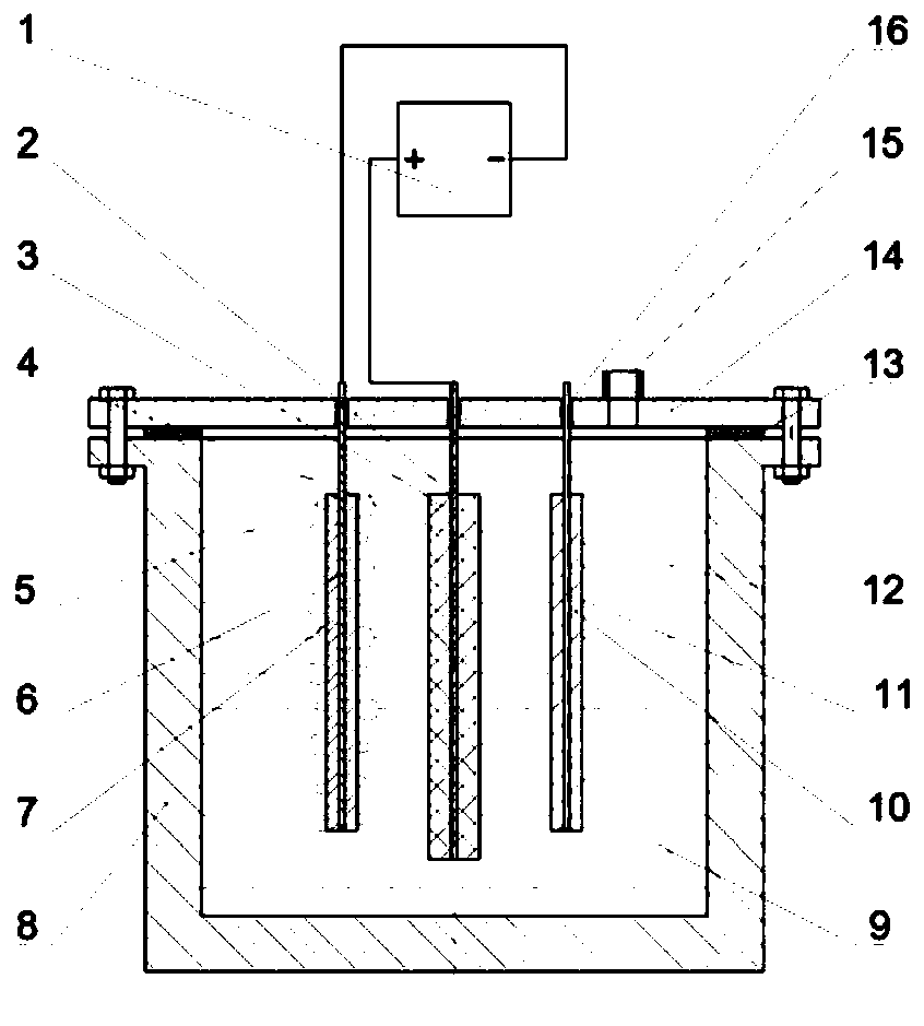
[0040] A double reaction electrode semi-electrolytic water splitting device. The device as figure 1 As shown, the device includes a power source 1, a capacitor electrode 2, a reaction electrode I5, an electrolytic cell 8, an electrolyte solution 9, a reaction electrode II10 and an electrolytic cell cover 14.

[0041] Such as figure 1As shown: there is a sealing ring I13 between the electrolytic cell 8 and the electrolytic cell cover 14, the electrolytic cell 8 and the electrolytic cell cover 14 are fixedly connected by bolts, the electrolytic cell cover 14 is provided with a gas collecting pipe 15, and the gas collecting pipe 15 communicates with the electrolytic cell 8; Electrolyte 9 is installed in electrolytic cell 8 , capacitive electrode 2 , reaction electrode I5 and reaction electrode II10 are arranged in electrolytic solution 9 , and reaction electrode I5 and reaction electrode II10 are located on both sides of capacitive electrode 2 .

[0042] Such as figure 1 As sh...

Embodiment 2

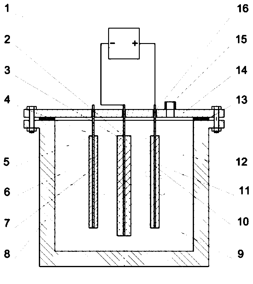
[0046] A double reaction electrode semi-electrolytic water splitting device. Except following technical parameter, all the other are with embodiment 1:

[0047] The reaction electrode I5 and the reaction electrode II10 are located on the other side of the capacitance electrode 2;

[0048] One side of the current collector I3 is closely attached to the capacitive electrode body 4;

[0049] The shape of the reaction electrode I5 is one of plate shape and grid shape;

[0050] One side of the current collector II6 is closely attached to the reaction electrode body I7;

[0051] The shape of the reaction electrode II10 is one of plate shape and grid shape;

[0052] One side of the current collector III11 is closely attached to the reaction electrode body II12.

Embodiment 3

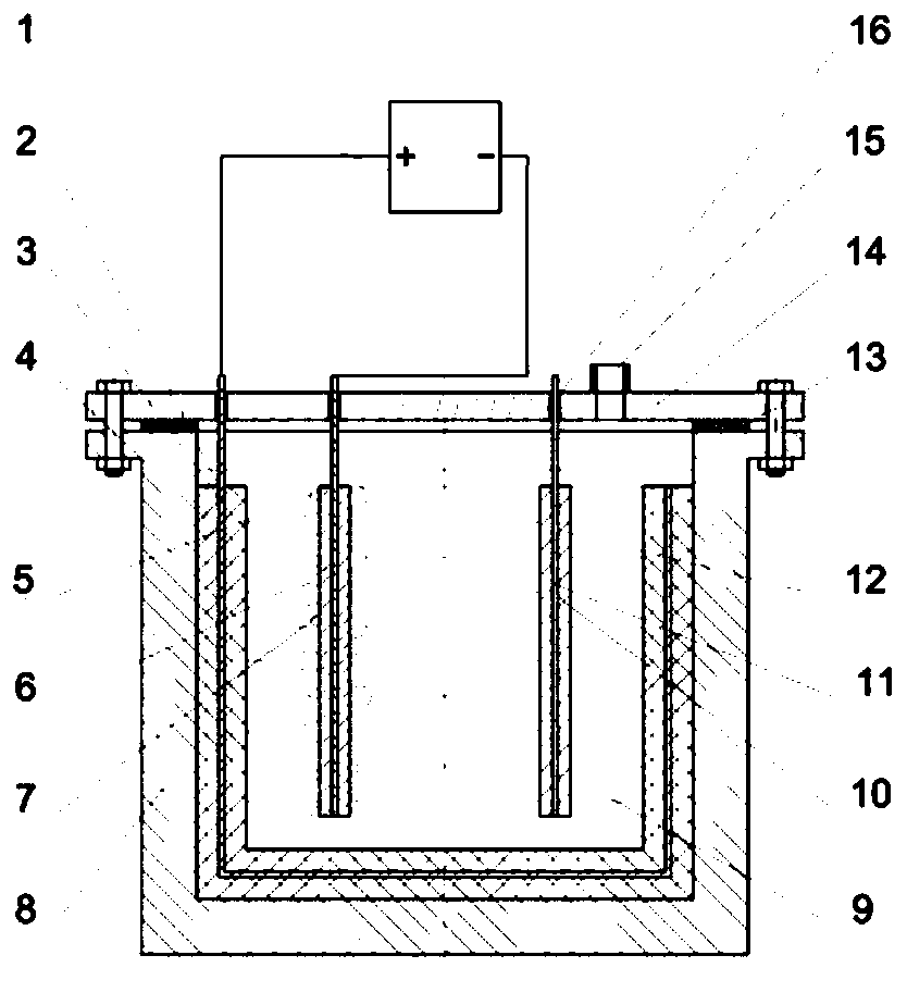
[0054] A double reaction electrode semi-electrolytic water splitting device. The device as figure 2 As shown, the device includes a power source 1, a capacitor electrode 2, a reaction electrode I5, an electrolytic cell 8, an electrolyte solution 9, a reaction electrode II10 and an electrolytic cell cover 14.

[0055] Such as figure 2 As shown: there is a sealing ring I13 between the electrolytic cell 8 and the electrolytic cell cover 14, the electrolytic cell 8 and the electrolytic cell cover 14 are fixedly connected by bolts, the electrolytic cell cover 14 is provided with a gas collecting pipe 15, and the gas collecting pipe 15 communicates with the electrolytic cell 8; Electrolyte 9 is installed in electrolytic cell 8 , capacitive electrode 2 , reaction electrode I5 and reaction electrode II10 are arranged in electrolytic solution 9 , and reaction electrode I5 and reaction electrode II10 are located on both sides of capacitive electrode 2 .

[0056] Such as figure 2 A...


PUM


Abstract

The invention concretely relates to a double-reaction-electrode water half-electrolysis device. The device is characterized in that a reaction electrode I (5) and a reaction electrode II (10) in an electrolytic tank (8) are located at two sides or the other side of a capacitor electrode (2); or the capacitor electrode (2) is laid on the inner wall and the bottom of the electrolytic tank (8), the electrolytic tank (8) provided with the capacitor electrode (2) is filled with an electrolyte (9), and the reaction electrode I (5) and the reaction electrode II (10) are located in the electrolyte (9). A current collector I (3) is connected with the positive electrode of a power supply (1), a current collector II (6) is connected with the negative electrode of the power supply (1), and hydrogen isevolved on a reaction electrode body I (7); or the current collector I (3) is connected with the negative electrode of the power supply (1), a current collector III (11) is connected with the positive electrode of the power supply (1), and oxygen is evolved on a reaction electrode body II (12). The device has the characteristics of avoiding of gas mixing, reduction of the device cost, increase ofthe electrolysis rate and significant reduction of the energy consumption for electrolysis.

Description

technical field [0001] The invention belongs to the technical field of semi-electrolyzed water devices. Specifically relates to a double reaction electrode semi-electrolyzed water device. Background technique [0002] As a zero-emission fuel and clean energy carrier, hydrogen has the highest specific energy of 143MJ kg -1 . Hydrogen can be used as the negative electrode reactant gas of the proton exchange membrane fuel cell, so that it can provide power for power electronic equipment. The positive electrode reaction gas of the proton exchange membrane fuel cell is oxygen. Currently, water electrolysis produces hydrogen and oxygen at two electrodes at the same time, requiring a diaphragm to isolate the hydrogen and oxygen. To prevent hydrogen and oxygen from permeating the membrane, a lower electrolysis current was applied (Q.Feng et.al., A review of proton exchange membrane water electrolysis ondegradation mechanisms and mitigation strategies, J.Power Sources 2017,366,33...

Claims


Application Information

Patent Timeline
IPC IPC(8): C25B1/04C25B9/06C25B11/00C25B9/17
CPCY02E60/36
Inventor 陈尧陈政
Owner WUHAN UNIV OF SCI & TECH
Why Eureka
Try Eureka