X-ray detector and charge emptying method

An X-ray and detector technology, applied in the field of detectors, can solve the problems of complicated emptying process, exposure conflict, long time consumption, etc., to simplify the exposure process, suppress the generation of interference charges, and speed up the exposure response ability.

Active Publication Date: 2019-06-21
SHANGHAI IRAY TECH
View PDF2 Cites 5 Cited by
  • Summary
  • Abstract
  • Description
  • Claims
  • Application Information

AI Technical Summary

Problems solved by technology

[0004] In view of the above-mentioned shortcomings of the prior art, the purpose of the present invention is to provide an X-ray detector and a charge emptying method, which are used to solve the problem that the emptying process of the existing X-ray detector is not only complicated and time-consuming, but also the problem of conflicting with the exposure

Method used


Image

  • X-ray detector and charge emptying method
  • X-ray detector and charge emptying method
  • X-ray detector and charge emptying method

Examples


Embodiment 1

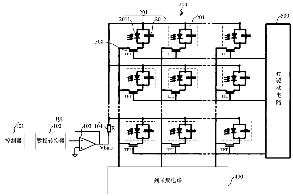
[0042] Such as figure 1 As shown, the present embodiment provides an X-ray detector, and the X-ray detector includes:

[0043] A bias voltage dynamic adjustment unit 100, configured to provide a negative bias voltage when the X-ray detector is in an exposure state; provide a forward bias voltage when the X-ray detector is in an idle state;

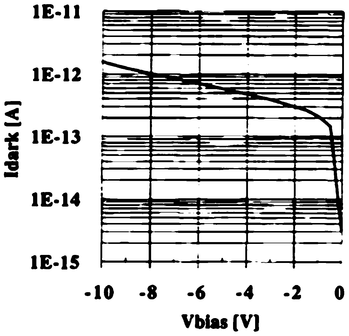
[0044] The photodetection unit 200 includes several photodetectors 201 arranged in an array, and each photodetector 201 is connected in parallel to the bias voltage dynamic adjustment unit 100, wherein the photodetector 201 includes a photodiode 2011 and a parallel connection The capacitor 2012 at both ends of the photodiode 2011; under the control of the negative bias voltage, the photodiode 2011 is in the reverse amplification region to realize photoelectric conversion; under the control of the forward bias voltage , so that the photodiode 2011 is in the forward blocking region to reduce its dark current.

[0045] This embodiment utili...

Embodiment 2

[0056] Such as image 3 As shown, this embodiment provides a charge clearing method implemented by using the X-ray detector described in Embodiment 1. The charge clearing method includes:

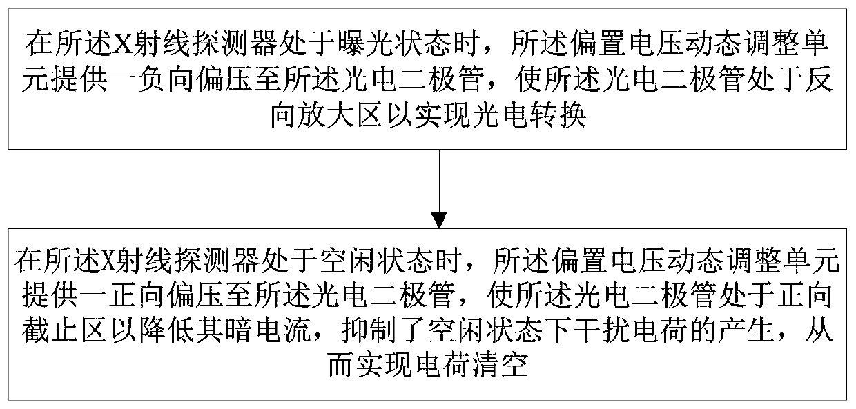
[0057] When the X-ray detector is in the exposure state, the bias voltage dynamic adjustment unit provides a negative bias voltage to the photodiode, so that the photodiode is in a reverse amplification region to realize photoelectric conversion;

[0058] When the X-ray detector is in an idle state, the bias voltage dynamic adjustment unit provides a forward bias voltage to the photodiode, so that the photodiode is in the forward cut-off region to reduce its dark current, suppressing In the idle state, the generation of interference charge is disturbed, so as to realize the charge emptying.

[0059] As an example, the method for realizing the dynamic adjustment of the bias voltage includes: detecting the state of the X-ray detector, and if the X-ray detector is in the exposure state, the d...


PUM


Abstract

The invention provides an X-ray detector and a charge emptying method. The X-ray detector comprises a bias voltage dynamic adjusting unit and a photoelectric detection unit, wherein the bias voltage dynamic adjusting unit is used for providing negative bias voltage when the X-ray detector is in an exposure state; a forward bias voltage is provided when the X-ray detector is in an idle state; the photoelectric detection unit comprises a plurality of photoelectric detectors arranged in an array, and each photoelectric detector is connected with the bias voltage dynamic adjustment unit in parallel, wherein each photoelectric detector comprises a photodiode and capacitors connected with two ends of the photodiode in parallel; the photodiode is located in a reverse amplification region under the control of the negative bias voltage so as to realize photoelectric conversion; and under the control of the forward bias voltage, the photodiode is placed in a forward cut-off region to reduce darkcurrent thereof. By the X-ray detector, the problems that when an existing X-ray detector carries out emptying operation, the emptying process is complex, consumed time is long, and furthermore, theemptying operation conflicts with exposure are solved.

Description

technical field [0001] The invention relates to the field of detectors, in particular to an X-ray detector and a charge emptying method. Background technique [0002] Digital Radiography (Digital Radiography, referred to as DR) is a new technology of X-ray photography developed in the 1990s. It is the leading direction of radiography technology and has been recognized by clinical institutions and imaging experts all over the world. The technical core of DR is the flat panel detector, which is a sophisticated and expensive device that plays a decisive role in the imaging quality. The flat panel detector is the X-ray receiving device in the DR system. In the DR system, the high-voltage generator and the ball tube control the output of the X-ray. The X-ray passes through the object and attenuates. The attenuated X-ray is transformed after passing through the flat panel detector. It is visible light, which is transformed into an electrical signal through photoelectric conversi...

Claims


Application Information

Patent Timeline
Patent Type & Authority Applications(China)
IPC IPC(8): A61B6/00H04N5/32H04N5/21
Inventor 陈泽恒马扬喜林言成黄翌敏
Owner SHANGHAI IRAY TECH
Why Eureka
Try Eureka