
Denitrification SCR ammonia injection control system and workflow thereof

A control system and workflow technology, applied in the field of SCR denitrification, can solve the problems of high labor intensity, high labor cost, large error and delay, etc., and achieve the effect of reducing labor intensity, high degree of intelligence, and simple workflow

Inactive Publication Date: 2019-06-21
DATANG ENVIRONMENT IND GRP
View PDF3 Cites 3 Cited by
  • Summary
  • Abstract
  • Description
  • Claims
  • Application Information

AI Technical Summary

Problems solved by technology

Although the PID control method has a good control effect in the linear control system, it does not affect the flue gas and NH 3 Under the action of the catalyst, the denitrification system with strong nonlinearity changes greatly with time, but it is difficult to obtain a good ammonia injection control effect.
The real-time performance of the measurement in the existing control method in the actual application of SCR denitrification is not good, with large errors and delays, and it is difficult to meet the requirements of real-time and precise control
In addition, the existing SCR control method can only be controlled manually, and operators need to monitor the discharge outlet NO for 24 hours. X Concentration, timely adjustment of denitrification ammonia injection amount, high labor cost, and high labor intensity

Method used


Image

  • Denitrification SCR ammonia injection control system and workflow thereof
  • Denitrification SCR ammonia injection control system and workflow thereof
  • Denitrification SCR ammonia injection control system and workflow thereof

Examples


Embodiment 1

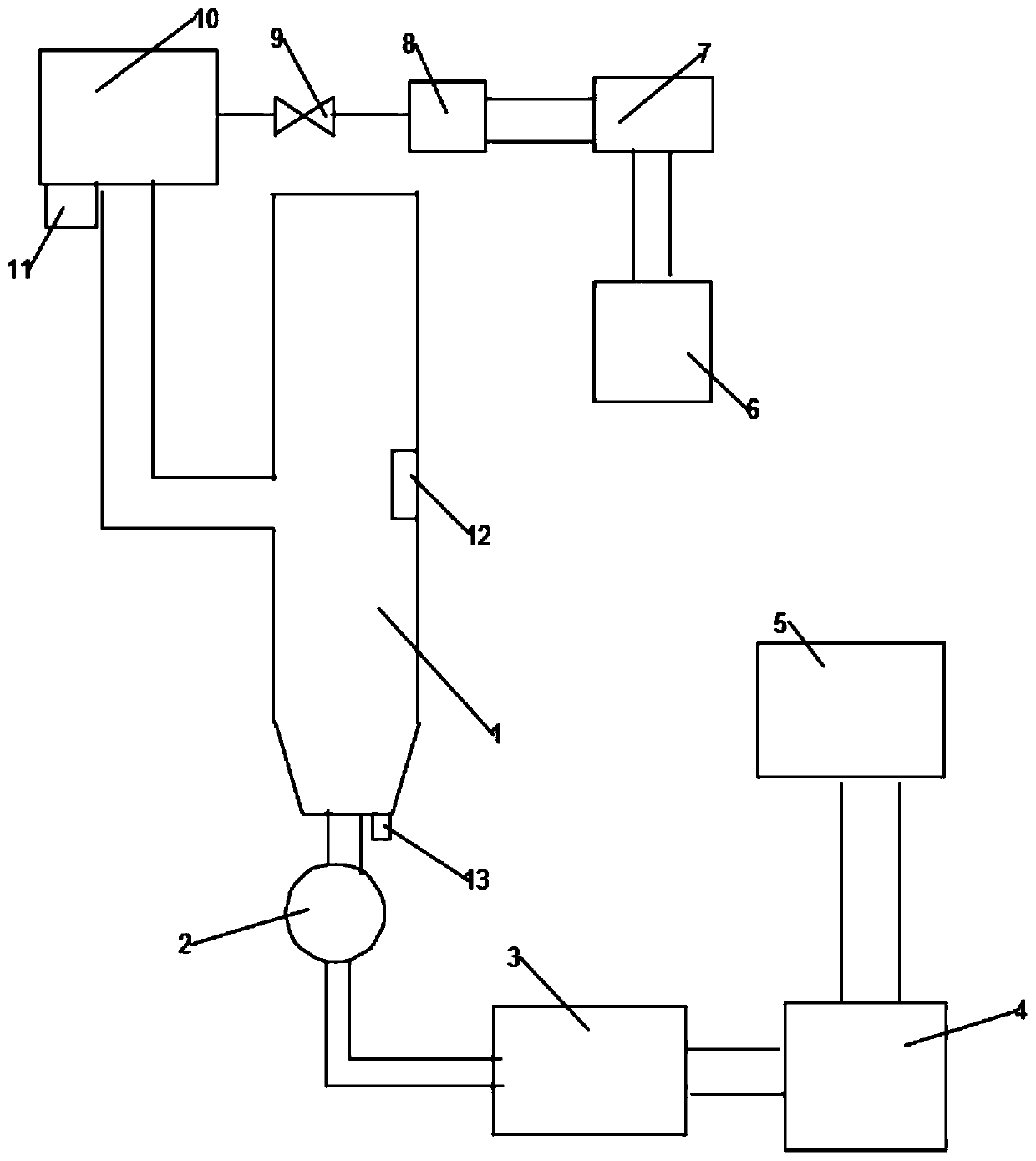
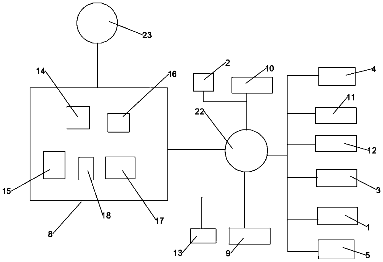
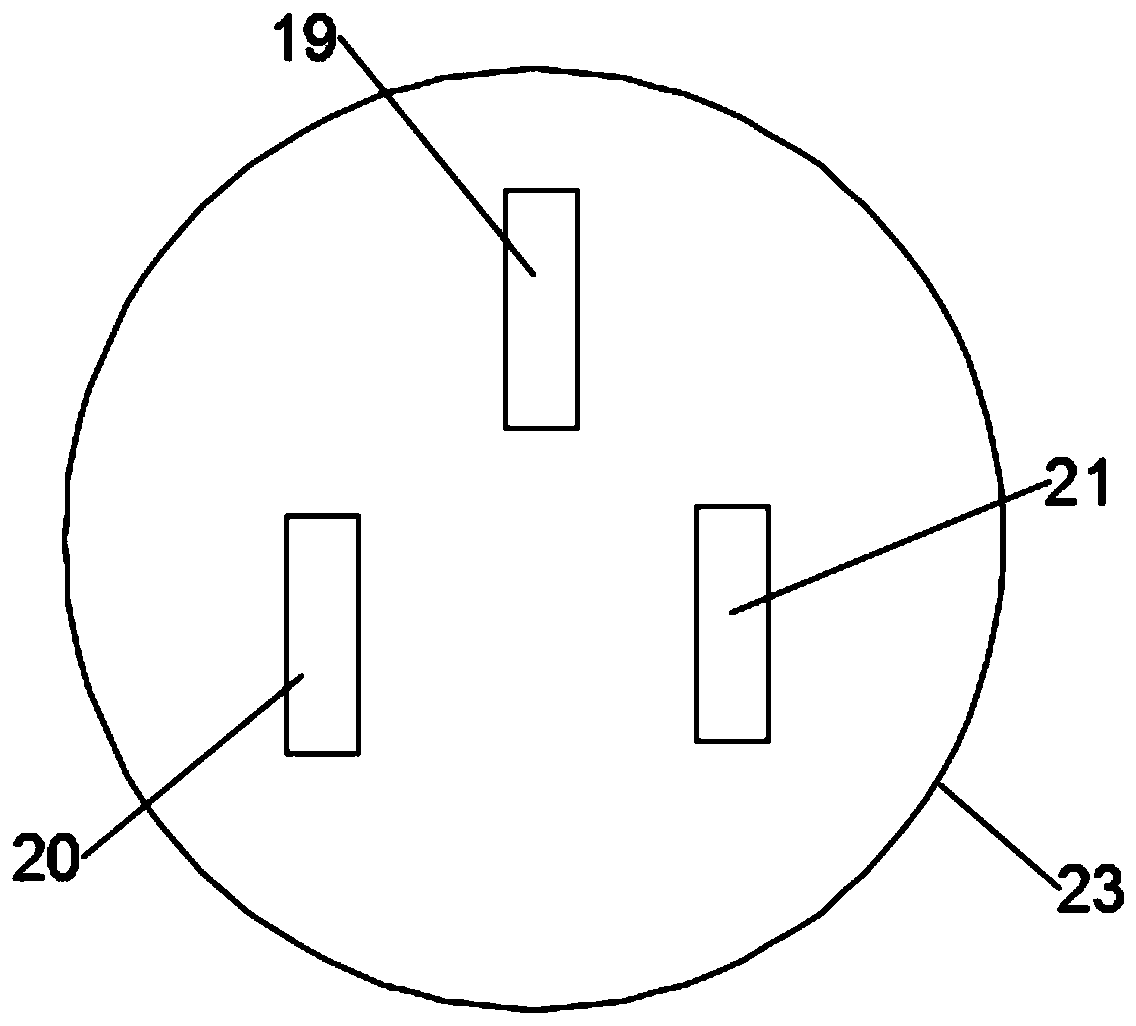
[0028] Example 1, such as Figure 1-3 As shown, a denitrification SCR ammonia injection control system according to an embodiment of the present invention includes: a control terminal 8, a mixing flowmeter 11, a thermometer 12, a flue gas flowmeter 13 and a solenoid valve 9, and the mixing flowmeter 11 is installed on the mixer 10 At the outlet of the mixer 10, the flow rate of the mixture of ammonia and air can be measured. The thermometer 12 is installed inside the SCR reaction tower 1 to control the reaction temperature. The solenoid valve 9 is located between the mixer 10 and the evaporator 7 to control whether Connected, the flue gas flowmeter 13 is located at the outlet of the SCR reaction tower 1, and measures the flue gas flow at the outlet in real time. The control terminal 8 communicates with the mixing flowmeter 11, the thermometer 12, the flue gas flowmeter 13 and the solenoid valve through the communication module 22 respectively. 9 connected. The control termina...

Embodiment 2

[0035]Embodiment 2, a denitrification SCR ammonia injection control system according to the embodiment of the present invention, including: control terminal 8, mixing flow meter 11, thermometer 12, flue gas flow meter 13 and solenoid valve 9, mixing flow meter 11 is installed in the mixer At the outlet of 10, the flow rate of the mixture of ammonia and air in the mixer 10 can be measured, the thermometer 12 is installed inside the SCR reaction tower 1, and the reaction temperature can be controlled, and the solenoid valve 9 is located between the mixer 10 and the evaporator 7, which can control Whether it is connected, the flue gas flowmeter 13 is located at the outlet of the SCR reaction tower 1, and measures the flue gas flow at the outlet in real time. The control terminal 8 communicates with the mixing flowmeter 11, the thermometer 12, the flue gas flowmeter 13 and the electromagnetic Valve 9 is connected. The control terminal 8 is also connected to the SCR reaction tower ...


PUM


Abstract

The invention discloses a denitrification SCR ammonia injection control system which comprises a control terminal, a mixed flow meter, a thermometer, a flue gas flow meter and a solenoid valve, wherein the mixed flow meter is mounted at an outlet of a mixer, the thermometer is mounted inside an SCR reaction tower, the solenoid valve is located between the mixer and an evaporator, the flue gas flowmeter is located at the outlet of the SCR reaction tower, and the control terminal is respectively connected with the mixed flow meter, the thermometer, the flue gas flow meter and the solenoid valvethrough a communication module. The invention further discloses a workflow of the denitrification SCR ammonia injection control system. The denitrification SCR ammonia injection control system disclosed by the invention has the benefits of being capable of instantly and quickly responding to automatically follow the adjustment of the denitrification ammonia injection amount and not requiring personnel to be monitored at all times, thereby reducing the labor intensity of the monitoring personnel.

Description

technical field [0001] The invention relates to the technical field of SCR denitrification, in particular to a denitrification SCR ammonia injection control system and a working process thereof. Background technique [0002] SCR (Selective Catalytic Reduction) denitrification technology is currently the most widely used and highly effective denitrification technology among various denitrification technologies. In our country, the SCR denitrification technology is mostly used in the denitrification technical transformation of power plants at present, and the denitrification efficiency can reach more than 80%. SCR technology mainly uses the reducing agent NH 3 with NO X The reaction produces harmless N 2 and H 2 O. [0003] The current control method in the practical application of SCR denitrification is still mainly based on the classic PID (proportional integral derivative) control. Although the PID control method has a good control effect in the linear control system,...

Claims


Application Information

Patent Timeline
Patent Type & Authority Applications(China)
IPC IPC(8): B01D53/90B01D53/86B01D53/56
Inventor 包文运张东平吴晔蔡志峰李光雷向朝虎王大钊李乐
Owner DATANG ENVIRONMENT IND GRP
Learn More