Glue feeding device with stirring function for LED lamp production

A technology of LED light and glue feeding, which is applied to mixers with rotating mixing devices, mixer accessories, and dissolving directions, can solve the problems of different glue quality, poor glue mixing effect, affecting the production quality of glue feeding devices, etc. The effect of production quality

Inactive Publication Date: 2019-06-21
肇庆市星动传说自动化技术有限公司
View PDF1 Cites 4 Cited by
  • Summary
  • Abstract
  • Description
  • Claims
  • Application Information

AI Technical Summary

Problems solved by technology

[0004] However, due to the relatively simple structure of the stirring device on the glue feeding device, the mixing effect of the stirring device on the glue is not good, so that the glue will still precipitate during long-term storage, resulting in different glue quality at different heights, which affects the glue feeding device. production quality

Method used


Image

  • Glue feeding device with stirring function for LED lamp production
  • Glue feeding device with stirring function for LED lamp production
  • Glue feeding device with stirring function for LED lamp production

Examples


Embodiment 1

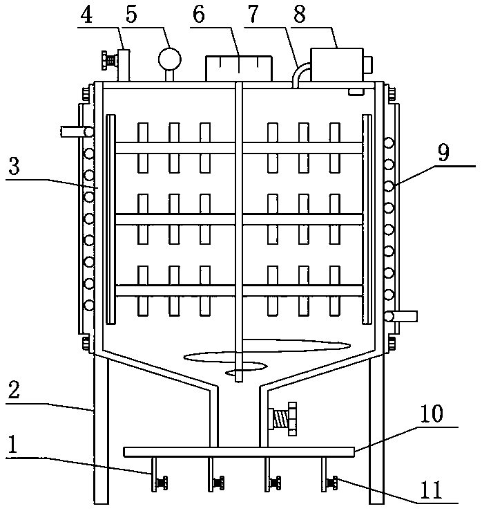
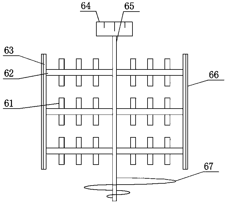
[0022] see Figure 1-Figure 4 , the present invention provides a kind of: a kind of glue feeding device for LED lamp production with stirring function, comprising a storage tank 3, a pressure gauge 5 is arranged on one end of the upper surface of the storage tank 3, and a rubber inlet pipe 4 is arranged on one side of the pressure gauge 5 The other end of the upper surface of the storage tank 3 is provided with an air pump 8, the connection between the storage tank 3 and the air pump 8 is provided with a first connecting pipe 7, and the dispensing device is also provided with a pressure sensor and a controller corresponding to the air pump 8, The use of pressure sensor, controller and air pump 8 is all prior art, and the bottom end of storage tank 3 is provided with main glue supply pipeline 10, and the lower surface of main glue supply pipeline 10 is provided with branch pipeline 1, and on branch pipeline 1 One end away from the main glue supply pipeline 10 is provided with a...

Embodiment 2

[0026] see Figure 1-Figure 4 , on the basis of Embodiment 1, in order to make the function of the glue feeding device more abundant, in this embodiment, preferably, the top of the storage tank 3 is provided with a temperature adjustment mechanism 9, and the temperature adjustment mechanism 9 includes a heat conduction base 91, and the heat conduction base 91 is provided with a heat pipe 92 at the junction of the storage tank 3, the top of the heat pipe 92 is provided with a water outlet pipe 93, and the bottom end of the heat pipe 92 is provided with a water inlet pipe 96, when the user needs to increase the temperature of the glue in the storage tank 3 , inject water with a temperature higher than the temperature of the glue from the water inlet pipe 96. At this time, the water heats the heat-conducting base 91 through the heat-conducting pipe 92, thereby heating the storage tank 3 through the heat-conducting base 91, thereby increasing the temperature of the glue in the stor...


PUM


Abstract

The invention discloses a glue feeding device with a stirring function for LED lamp production and belongs to the technical field of LED lamps. The glue feeding device comprises a storage tank, a pressure gage is arranged at one end of the upper surface of the storage tank, a glue feeding pipe is arranged on one side of the pressure gage, an air pump is arranged at the other end of the upper surface of the storage tank, a first connecting pipe is arranged at the connection of the storage tank and the air pump, a main glue supply pipeline is arranged at the bottom end of the storage tank, a branched pipeline is arranged on the lower surface of the main glue supply pipeline, a first valve is arranged at the end, far away from the main glue supply pipeline, of the branched pipeline, and supporting legs are arranged on two sides of the storage tank. A stirring mechanism is arranged on the glue feeding device, so that a user can stir glue in the storage tank through a stirring rod, a spoiler and spiral blades on the stirring mechanism, so that the condition that a precipitate is generated as glue is stored for a long time is avoided, glue in different height layers is consistent in quality, and therefore, the production quality of the glue feeding device is guaranteed.

Description

technical field [0001] The invention belongs to the technical field of LED lamps, and in particular relates to a glue feeding device for LED lamp production with a stirring function. Background technique [0002] The LED lamp is an electroluminescent semiconductor material chip, which is cured on the bracket with silver glue or white glue, and then connected to the chip and the circuit board with silver or gold wires, and sealed with epoxy resin around it to protect the inner core wire. The role is to install the shell at last, and the LED lamp needs to be dispensed during the production process. [0003] The Chinese patent (publication number CN208592014U) discloses a special glue feeding device for LED lamp production, including a frame body, a glue storage tank, a glue inlet pipe and a glue outlet. The glue storage tank is fixed on the frame body, and the top of the glue storage tank The sealing cover is fixedly connected, and the sealing cover is connected with the rubb...

Claims


Application Information

Patent Timeline
Patent Type & Authority Applications(China)
IPC IPC(8): B01F7/18B01F7/24B01F15/00B01F15/06
Inventor 叶卫超陆思如
Owner 肇庆市星动传说自动化技术有限公司
Why Eureka
Try Eureka