Foam light soil pouring retailing backwall structure in highway reconstruction and extension project and construction method thereof

A foam lightweight soil and expressway technology, which is applied to buildings, roads, roads, etc., can solve problems such as inability to effectively solve construction problems, and achieve the effects of universality, speeding up the construction process, and convenient construction.

Active Publication Date: 2019-06-21
SHANDONG UNIV
View PDF4 Cites 7 Cited by
  • Summary
  • Abstract
  • Description
  • Claims
  • Application Information

AI Technical Summary

Problems solved by technology

Therefore, the inventor found that: this construction method cannot effectively solve the constructi...

Method used


Image

  • Foam light soil pouring retailing backwall structure in highway reconstruction and extension project and construction method thereof
  • Foam light soil pouring retailing backwall structure in highway reconstruction and extension project and construction method thereof
  • Foam light soil pouring retailing backwall structure in highway reconstruction and extension project and construction method thereof

Examples


Embodiment 1

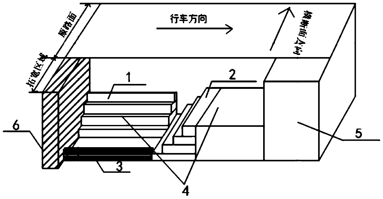
[0049] Step 1. First, measure the width and height of the subgrade at the back of the abutment in the widened road section on site, and design the step size of the cross section and longitudinal section to be excavated for the subgrade at the junction in combination with the site construction requirements and the construction specifications of the foam light soil, such as figure 1 As shown, among them, the height from the bottom of the foundation pit at the back of the platform to the original road surface is 4.85m, and the height of the road bed and road surface is reserved at the upper part along the driving direction, that is, 2.05m (the road bed is 1.2m, and the road surface thickness is 0.85m). Set 4 steps, each step is 0.7m high and 1.4m wide, and the width of the base from the back of the platform to the first step along the driving direction is 4.5m; along the direction of the cross section, set 4 steps near the middle line of the road, each step The height is 0.7m, the...

Embodiment 2

[0056] 1. The backfill structure model of the abutment is as follows: Figure 5 as shown,

[0057] This numerical simulation model is as Figure 5 , the thickness of each structural layer has been Figure 5 shows that the groundwater table is 4m below the surface. When simulating the consolidation settlement of embankment fill, the simulation method of layered filling is adopted, each layer is loaded with a thickness of 0.7m, and then the second layer is loaded, and so on. The total height of embankment filling is 4.2m, of which foam lightweight soil material is used for the section close to the abutment, and embankment filling is used for the end far away from the abutment.

[0058] 2. Collation of data results

[0059] (1) Comparison of the settlement of foam light soil and conventional filling after 30 days (the density of light soil is 1.1g / cm 3 )Such as Image 6 shown.

[0060] It can be seen from the above results that at the junction of the transitional section o...


PUM

PropertyMeasurementUnit
Lengthaaaaaaaaaa
Densityaaaaaaaaaa

Abstract

The invention relates to a construction method of pouring a retailing backwall using foam light soil in a highway reconstruction and extension project. Firstly a base is cleaned and compacted, a layerof broken stones with the thickness of 30 cm is laid, steps are arranged along the route driving direction and along one side, close to a road center line, of the cross section direction, a convex step is poured by using a form hanger on the side close to a side slope, and the steps are arranged for better lapping of the foam light soil and subgrade soil. Waterproof geomembranes are laid on the lowest layer and the topmost layer of a foam light soil structure, and earthwork standard rooms are laid on the positions which are respectively 50 cm from the bottom layer and 50 cm from the top layerto enhance the overall strength. By adopting the construction method, under the condition that the area at the retailing backwall is small and is not favorable for construction of a large-scale instrument, the construction can be simplified, the operation is convenient, by utilizing the features of quick early strength formation and good integrality of the foam light soil, the dependency on lateral wrapping soil is reduced, and template supports are used instead for pouring. The construction method has a relatively good effect on reducing bump at bridge-head.

Description

technical field [0001] The invention belongs to the field of road engineering, in particular to a platform back structure poured with foam light soil in expressway reconstruction and expansion projects and a construction method thereof. Background technique [0002] With the increase of traffic volume, more and more expressways have begun to implement reconstruction and expansion projects. For the abutment backfill project in the reconstruction and expansion of expressways, how to reduce the differential settlement between the abutment and the road surface at the junction, so as to effectively It is very important to alleviate the problem of "jumping at the bridge head". Gravel is mostly used as traditional backfill material, but its fluidity and strength need to be improved. In addition, in the construction process of the traditional method, due to the too close distance between the back of the table and the structure and the narrow working surface, it becomes a weak link ...

Claims


Application Information

Patent Timeline
IPC IPC(8): E01C3/00E01C3/04
Inventor 蒋红光王立旗姚占勇刘兆新柳春生刘源张吉哲梁明
Owner SHANDONG UNIV
Why Eureka
Try Eureka