Cement paste concentration real-time regulation and control device for cement-soil mixing pile and use method thereof

A cement-soil mixing pile and real-time control technology, which is applied to sheet pile walls, buildings, and infrastructure engineering, can solve the problems of cement waste, poor drilling in hard soil layers, and the inability to judge the degree of softness and hardness of the soil layer. Improve the strength of cement and soil, reduce the cost of the project, and improve the effect of construction efficiency

Active Publication Date: 2019-06-21
SOUTHEAST UNIV +1
View PDF7 Cites 6 Cited by
  • Summary
  • Abstract
  • Description
  • Claims
  • Application Information

AI Technical Summary

Problems solved by technology

[0003] The currently used cement-soil mixing piles rely entirely on manual control for construction. Operators cannot perceive changes in the softness and hardness of the soil layer on the pile driver, and cannot judge the actual situation of the softness and hardness of the soil layer when the pile driver is drilling.
In addition, the cement slurry used in the construction of cement-soil mixing piles is mixed in batches accordi

Method used


Image

  • Cement paste concentration real-time regulation and control device for cement-soil mixing pile and use method thereof
  • Cement paste concentration real-time regulation and control device for cement-soil mixing pile and use method thereof
  • Cement paste concentration real-time regulation and control device for cement-soil mixing pile and use method thereof

Examples


Embodiment 1

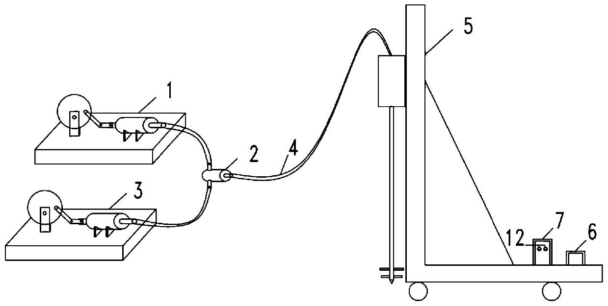
[0029] Such as figure 1 As shown, a cement-soil mixing pile cement slurry concentration real-time control device includes a current sensor, a monitoring host 6, a slurry pump 1, a frequency conversion pump 3 and a tee joint 2, and the current sensor is installed in the control cabinet 7 of the pile driver. Before use, adjust the original current analysis program in the monitoring host according to the geological survey data of the construction site and local construction experience. After the test pile debugging confirms that it can operate normally, the cement-soil mixing pile construction can be started. During construction, the current sensor collects the current value of the drill pipe inside and outside the pile driver and transmits it to the monitoring host. The monitoring host analyzes the current value and change characteristics, obtains the softness and hardness of the soil layer at the depth of the drill bit, and calculates that the soil layer reaches the design stren...

Embodiment 2

[0032] A city road foundation treatment project is designed to use two-way cement-soil mixing piles for reinforcement. The design pile length is 12m, pile diameter is 600mm, pile spacing is 1.5m, and the characteristic value of the bearing capacity of the composite foundation is 85kPa. Geological survey data show that the soil layers of the site from top to bottom are: ②-1 layer: silt, layer thickness 2.2-3.5m; ③-1 layer: clay, layer thickness 3.5-4.8m; ④-1 layer: silt, layer thickness About 3.0m; ④-2b layer: clay, layer thickness 2.0-3.0m. The characteristic values ​​of natural foundation bearing capacity of the above four soil layers are 40kPa, 120kPa, 40kPa and 130kPa respectively.

[0033]The on-site two-way cement-soil mixing pile machine is equipped with a cement slurry concentration real-time control device, and the current analysis program is compiled according to the geological survey data, installed in the monitoring host 6, and the construction starts after the test...

Embodiment 3

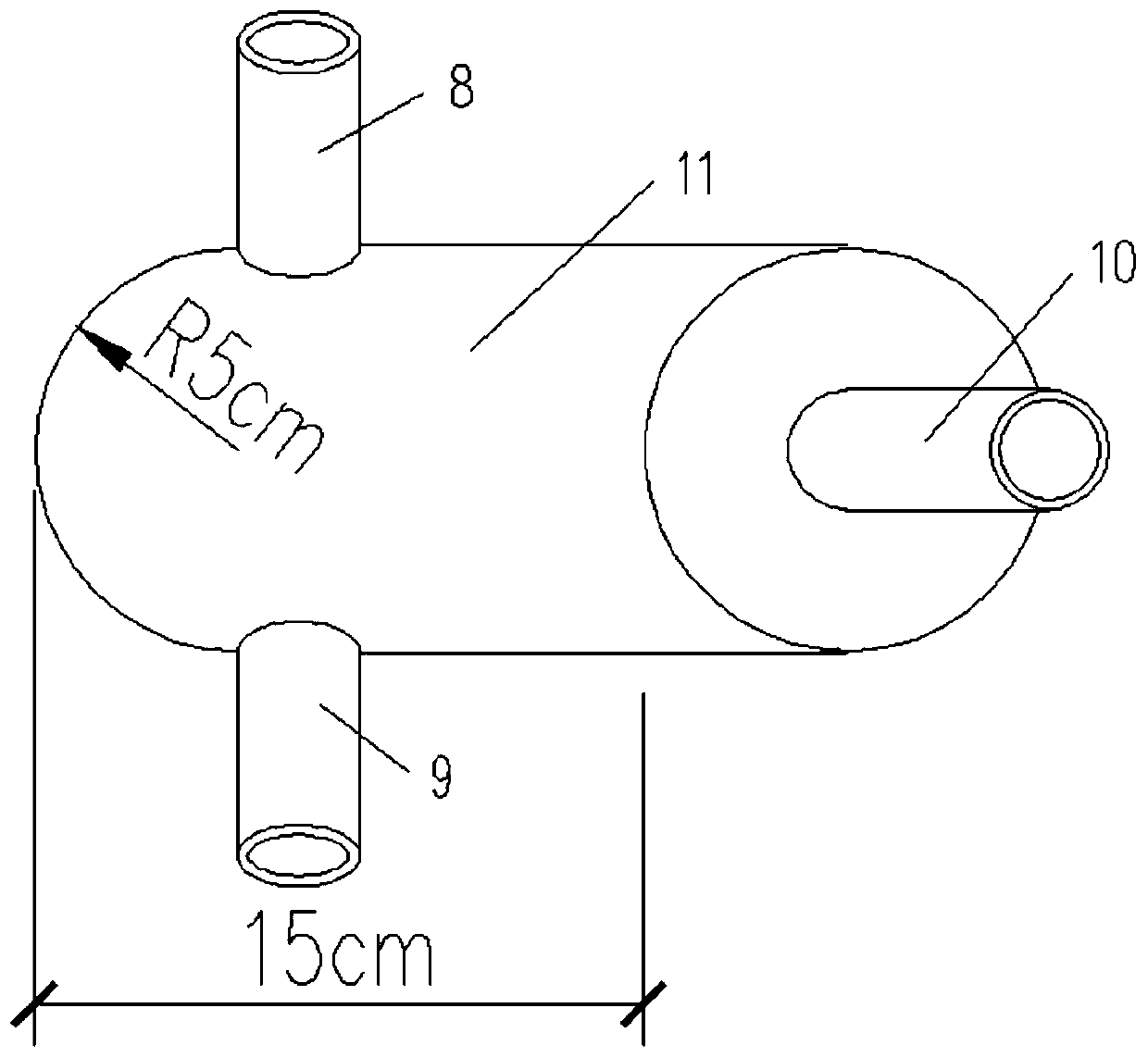
[0041] Such as figure 2 As shown, the tee joint 2 is a cylindrical chamber in the middle of the joint, with a cross-sectional radius of 5 cm and a length of 15 cm. The cement slurry and water enter the tee joint from the slurry inlet 8 and the water inlet 9 respectively, and under the action of the pumping pressure Next, after the cement slurry and water mixing chamber 11 are mixed quickly and evenly, the three-way joint 2 is sprayed out from the slurry outlet 10, and is transported to the cement-soil mixing pile machine 5 through the slurry delivery hose 4.

[0042] The purpose of the present invention is to provide a real-time control device for the cement slurry concentration of the cement-soil mixing pile and its use method, so as to adjust the cement slurry concentration in real time according to the actual soil layer softness and hardness at the depth of the drill bit, so as to ensure the maximum utilization of the soil layer in the soft soil layer The water in the wate...


PUM

PropertyMeasurementUnit
Radiusaaaaaaaaaa
Layer thicknessaaaaaaaaaa

Abstract

The invention discloses a cement paste concentration real-time regulation and control device for a cement-soil mixing pile and a use method of the cement paste concentration real-time regulation and control device. The device comprises a paste feeding pump, a three-way joint, a variable frequency water pump, a paste feeding hose, a cement-soil mixing pile machine, a monitoring host, a pile machinecontrol cabinet and a current sensor. The method comprises the following steps: analyzing and summarizing a corresponding relation between current and soil layers according to geological explorationdata of a construction site and local construction experience before use, determining a cement mixing amount required by each soil layer to reach design strength, and inputting the cement mixing amount into a current analysis program; after confirming that the device can normally operate through pile testing debugging, starting a pile driver for construction; and during construction, always keeping the device in a power-on state until the construction is finished. The concentration of the cement paste is adjusted according to the hardness of the actual soil layer, so that the cement paste withhigher concentration is sprayed to the soft soil layer, the cement paste with lower concentration is sprayed to the hard soil layer, the cement soil strength of the soft soil layer and the construction efficiency of the hard soil layer are improved, and the application effect of the cement-soil mixing pile composite foundation is improved.

Description

technical field [0001] The invention relates to the technical field of geotechnical engineering, in particular to a real-time control device for cement slurry concentration of a cement-soil mixing pile and an application method thereof. Background technique [0002] Cement-soil mixing pile technology is a soft soil foundation reinforcement method widely used at home and abroad. Its principle is to spray slurry into the soil layer while drilling through a special deep-layer mixing machine, and force the soft soil and curing agent to stir on the spot. A series of physical-chemical interactions between the curing agent and the soft soil form a cement-soil column with high strength, integrity, and good water stability. In engineering practice, most of the soil layers of the site to be treated are distributed in layers, and the soil layers are uneven in hardness. Weak soil layers usually have a high water content, and to achieve the purpose of reinforcement, more cement slurry i...

Claims


Application Information

Patent Timeline
IPC IPC(8): E02D5/46E02D15/04
Inventor 朱志铎万瑜高波胡红成周辉刘锦平张晓俊钱叶存程华敏舒翰璋蔡卫东王庚午谭龙陈光华
Owner SOUTHEAST UNIV
Why Eureka
Try Eureka